 Eric Ljungquist
NMOS-Resistor Logic, Dynamic Logic
This log goes over what I call the basic building blocks of the circuit.
I chose NMOS logic as it seemed very straight forward to design with. I've also seen a lot of designs using BJT Transistor-Transistor Logic to build discrete component circuits and I wanted to do something a bit different.
Basic Logic Gates

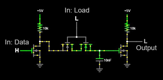
D Latch
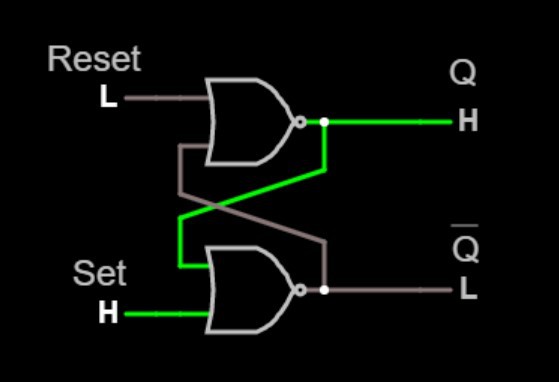
SR Latch
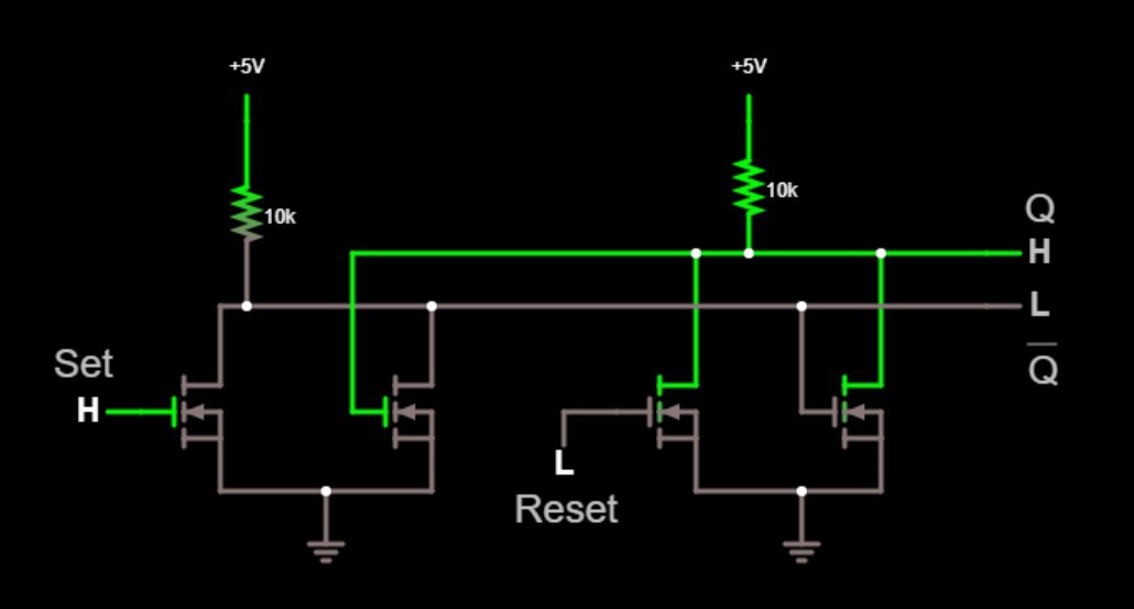
The SR latch is a simple way save a state. e.g. "Do I have data in the buffer I need to send?" or "Am I currently sending out a data packet?". I used the typical two cross coupled NOR gates to implement mine. At power up the latch will start in an unknown state. I've added an additional pull down mosfet to the "Set" side of the latch to act as an additional input for the power-on-reset circuit.
The transistor level diagram:
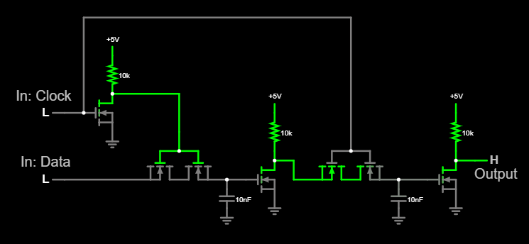
D Flip-Flop
For the D Flip-Flop we are just doubling up the D Latch shown above in a master-slave configuration but with a slight change to the Load input. This prevents the flip-flop from being "transparent" while clocking in the data signal.
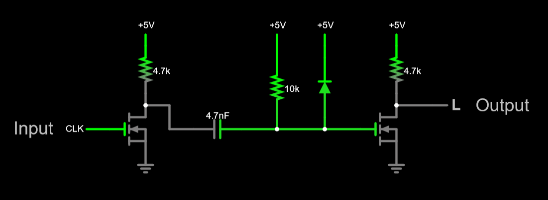
Edge Detector
Discussions
Become a Hackaday.io Member
Create an account to leave a comment. Already have an account? Log In.