Yesterday night,
before I went to bed, I thought:
- Direct modelling makes it easy to adjust some things and hard to adjust others (that would depend on some sort of history).
- Code modelling makes non-fragile models but 2D sketching would get complex quickly.
- Fusion 360's top down approach is nice, but being limited to 1 timeline means that components that aren't dependent on each other still have to be modelled one after the other.
and so I thought "what about node based CAD?"
The first Google result was very promising: https://lesterbanks.com/2015/06/antimony-a-free-node-based-3d-cad-modeling-tool/
 I was never a fan of the spline lines though. For me, it just makes the nodes look tangled. I'm thinking of a metro map or PCB layout UI that makes the whole thing look neater and less "spaghetti node".
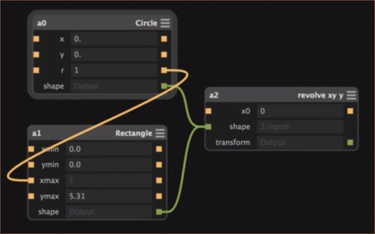
Anyway, I posted the link in the 3D Printing Discord and the next day, I also got Elephant (MoI3D), Grasshopper (Rhino) and Dynamo as suggestions.
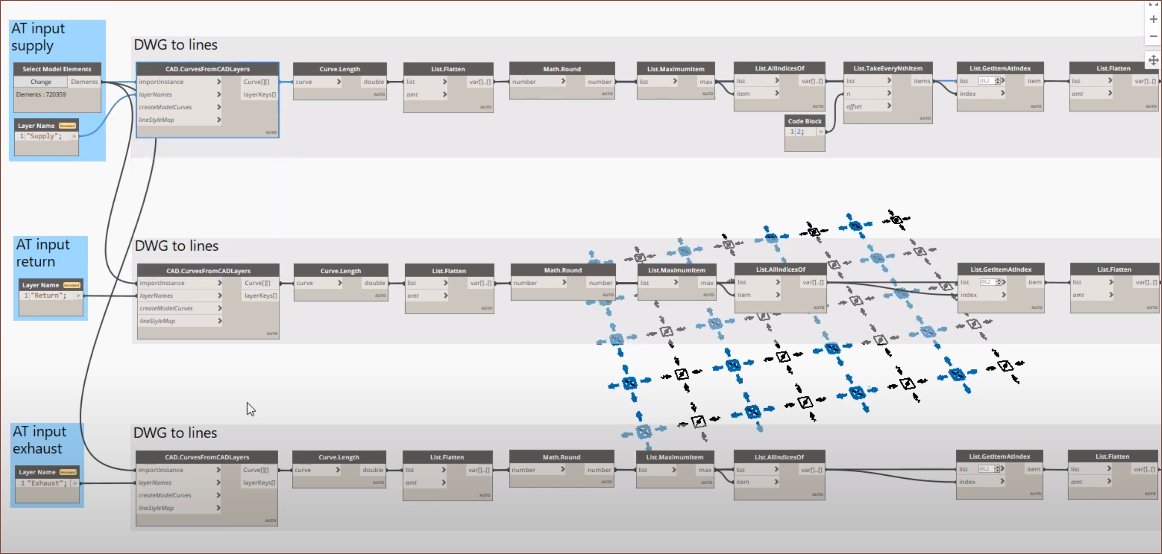
Dynamo looks very close to the idea I was thinking of last night, where you have multiple "timelines" and you can see the model behind them all. I was also thinking of having the option of a vertical timeline. I also want some sort of feature sync feature (or an easy workflow to keep them synchronised) with another similar part.
Example Workflow
The axis sliders from gd0036 will be the first workflow I'll try and make into a node based timeline from, as they are derived from very similar parts that only differ in the diameter of the tube very early in the model.
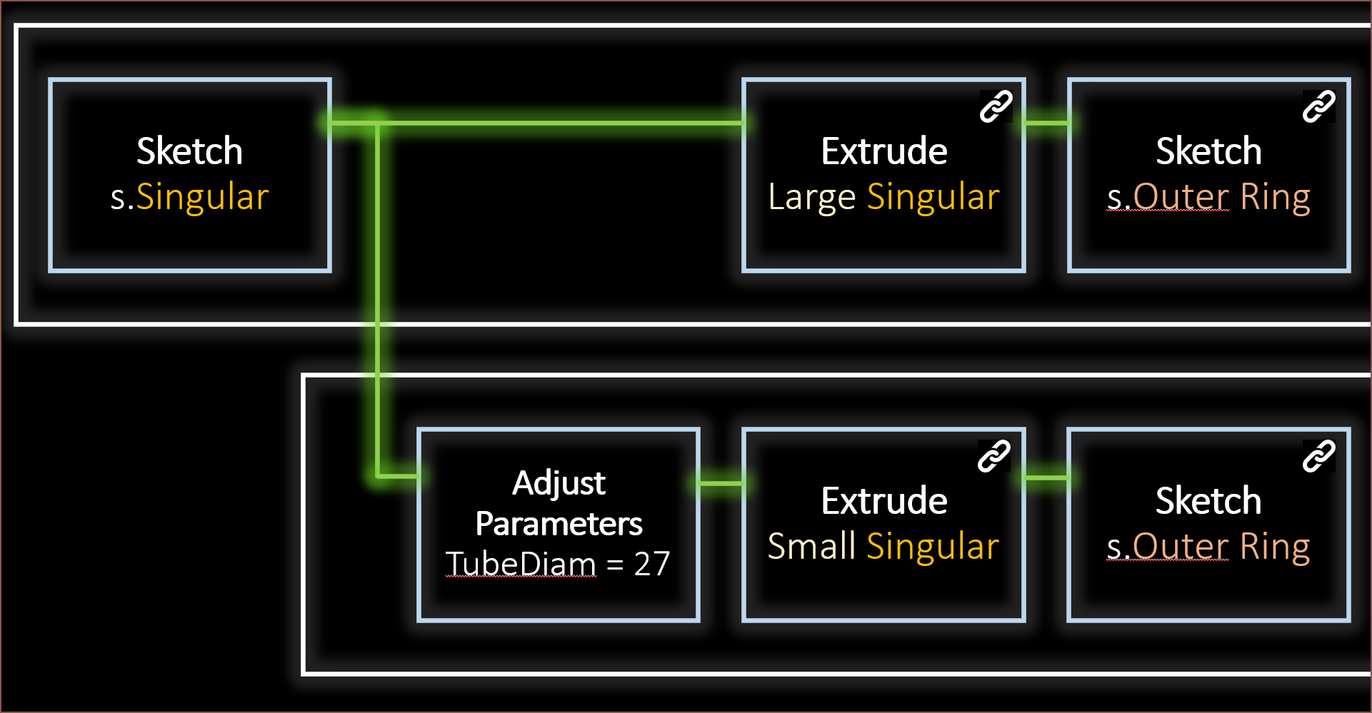
 I think the most straigtforward approach is to have a sketch node that goes into a node that makes a tweak to one of the parameters and outputs that new sketch. In this case:
 where:
- All nodes have their own subsystem of nodes.
- "Adjust Parameters" adjusts the parameters used in the input sketch.
- Nodes with chain icons try to sync their features together.
- The main problem for extrudes is when the amount of available profiles change and how to go about understanding the design intent or getting it from the user without asking too many questions.
- A similar problem could crop up for sketches. I'm thinking that there should be something similar to CADquery selections when choosing what lines and faces are projected to the sketch, and make that a node so that you don't have to touch it if the software deduces correctly, and can make tweaks if needed.
- Coloured text are timeline string variables created on the fly.
- so I can start typing "sing" and enSketchen gives me the option of making it just text, making it a timeline variable or selecting the variable "Singular". This should be sorted by highest probability.
- This is so that if a user decides on a new name for a part or sketch, all the subsequent feature names can be automatically changed.
- There might need to be a timeline freeze button, so that a user can work on, fix and/or sort out the features for one part and then sync changes with other timelines.
Performance
Multiple timelines should also make multithreaded computes more viable. Ideally, I would also like to use an implicit CAD approach for further performance gains. I'm also thinking of an "Expose" node, where it makes a... actually it's more like an "Export" node, where a seperate enSketchen file is created that is synced to the node timeline. This is so that parts can be imported into other components without having to import everything from the previous file, potentially improving performance. "Export" could also have subnodes, so that it's possible to do things like reorientate a part before auto exporting it, which will be useful for projects that have a lot of parts that need to be printed.
Sketches
Nodes in sketches will make 2D sketching more parametric than they are currently. For example, scripts could be moved around in the order when they are executed, and parameters can be piped to them. Maybe a "solve for" input might be needed, so that a solution can be found to fufill a constraint instead of having a parameter. Another example are sketch fillets and chamfers. I think it would be nice to have sketch fillets that work like their 3D counterpart in Fusion 360.
Each sketch node will have a menu where all its related constraints are. I think that's better than a large list of contraints and trying to select that one contstraint nested under 5 other coincidents. Ideally, I'd also like to have some sort of "construction selection", for those times when I only want parts of a circle or rectange as construction but I don't want to break the lines and turn them into arcs or lines with coincidents dotted about.
The sub-node of a sketch will start with a plane node. This should have a "flip" toggle so that the plane can be facing the intended way. The plane would act like a planar constraint to everything that's connected to it. It's a node, meaning that more than one plane can be in a sketch. This is useful for features like loft and sweep that usually require multiple sketches in current CAD software to generate. It also means that sketches are intended to be 3D compatible. Helixes come to mind.
Icons and Fonts
I also want to see what can be done to make parametric icons and fonts with this method. Watching through a few FreeCAD iconpack creation efforts, it does seem like icon lines and colours could be parameterized to speed up icon creation, and allow for tweaks and changes such as line widths or fillet radii.
[Published at 10:13]
[14:45]
Related Videos
The above is a video I found just now, which shows that nodes can be used for precision or organic shapes.
I saw this video a while ago but didn't make the connection. Well, this was before even thinking of this project so there was no connection to make.
 kelvinA
Discussions
Become a Hackaday.io Member
Create an account to leave a comment. Already have an account? Log In.