Vini's Lab
-
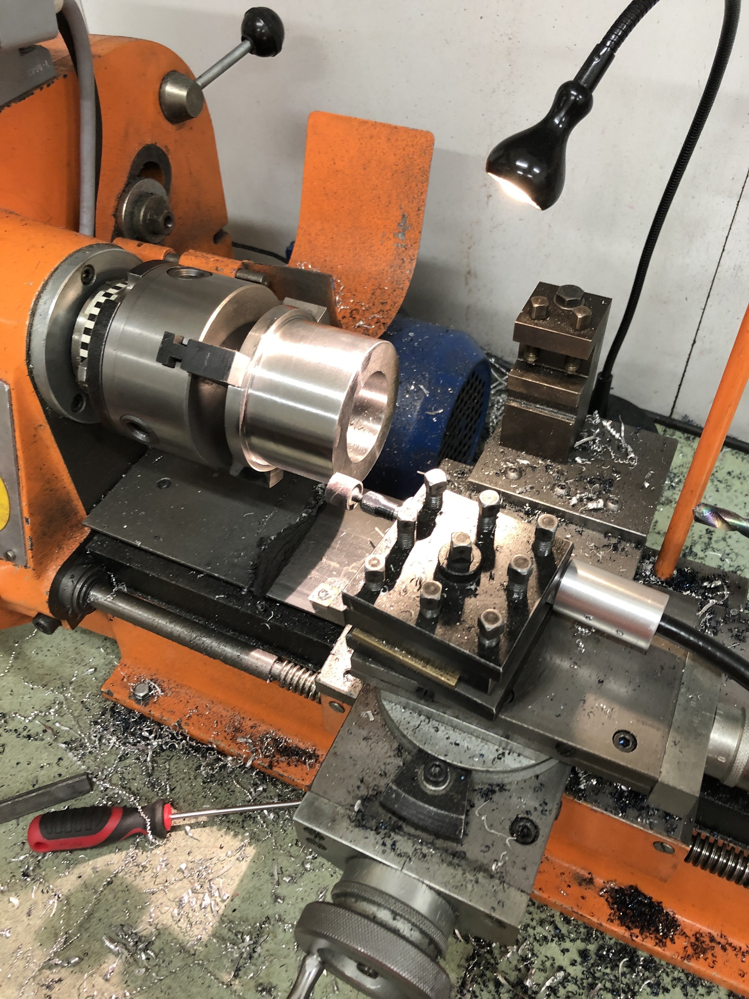
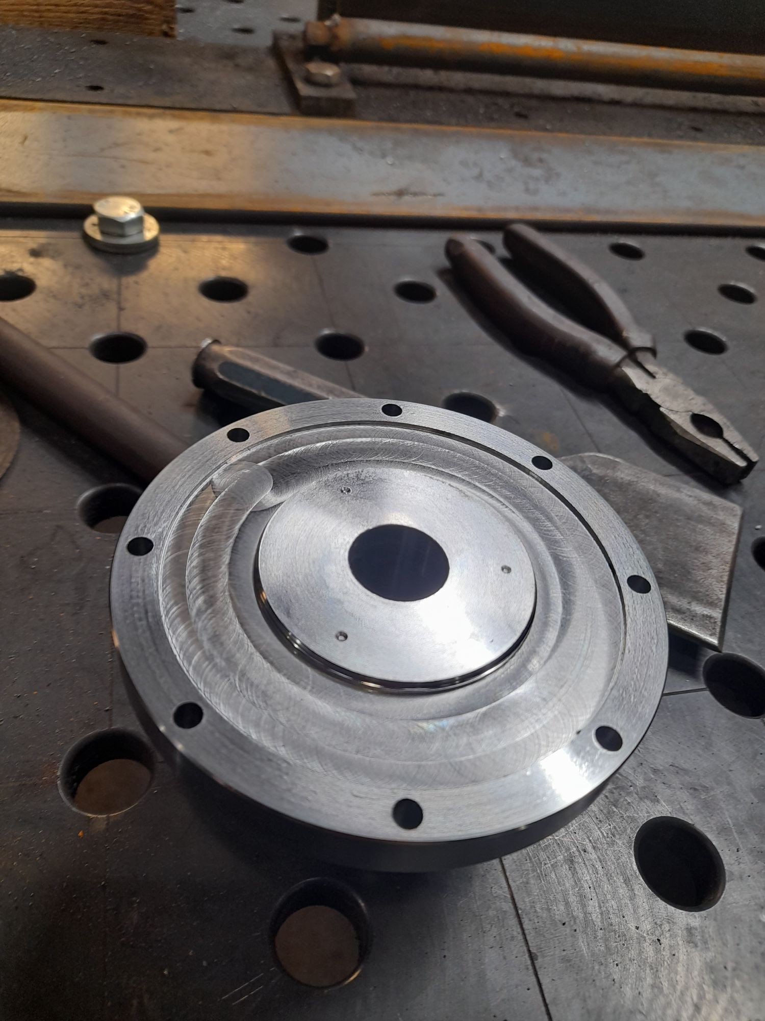
Wehnelt machining attempt
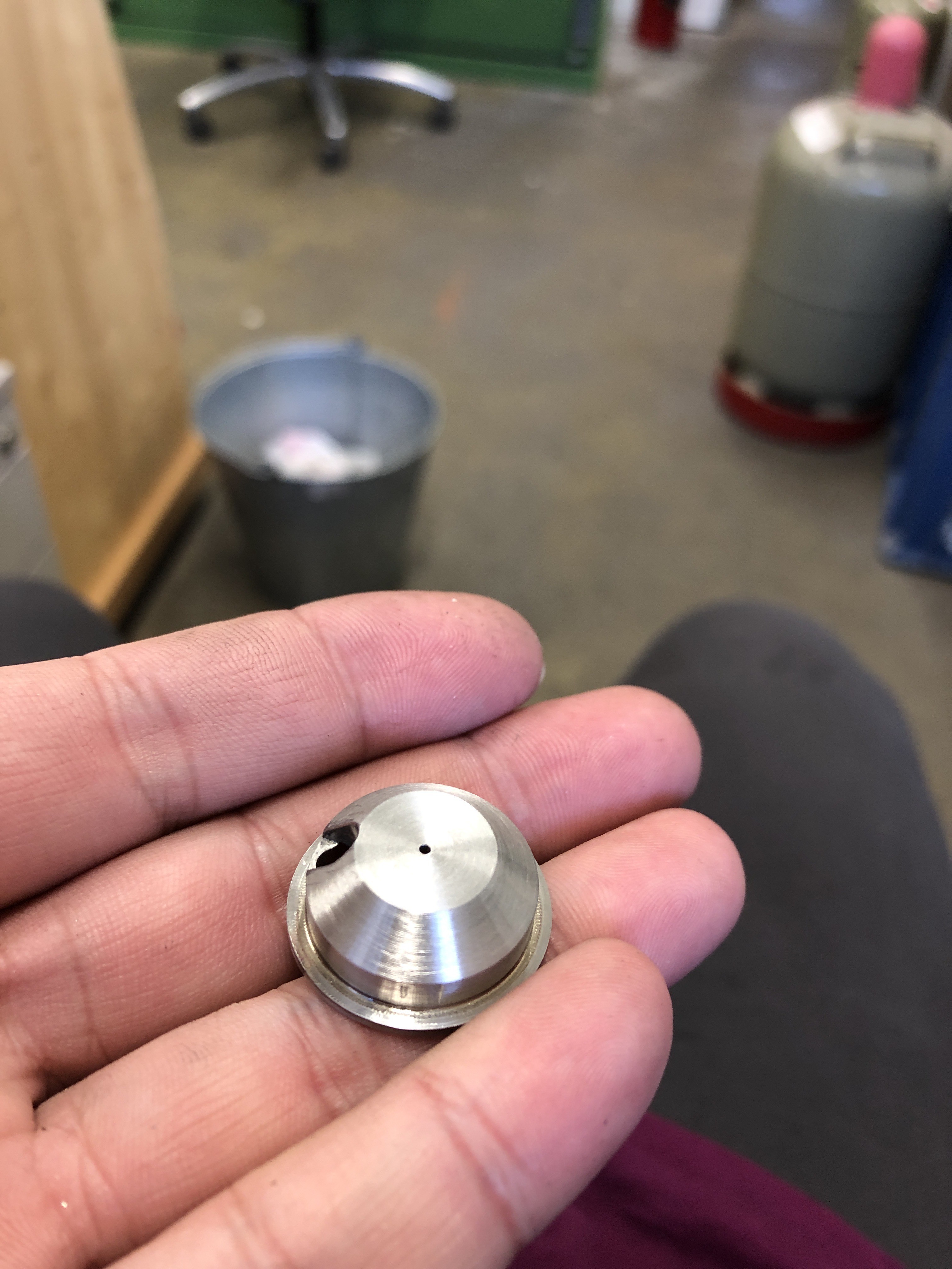
04/07/2022 at 17:06 • 0 commentsThe Wehnelt was a bit harder to machine than I had imagined.
The problem is the ID is too small so tool clearance is an issue.
I had to use a 14mm drill to create the hole to clear the tungsten filament.
The venting hole was supposed to be perpendicular with the chamfer, but I don't have a good way to machine it in angle and rotate the right amount so I decided for this lateral milling and drilling operation that worked well, only problem I did not make a mandril to hold it so clamping from the edge distorted the part that does not get flush with the filament ceramics plate.
Also the tip of the filament is reaching out the small hole, so I will need to adjust the part height.
![]()
-
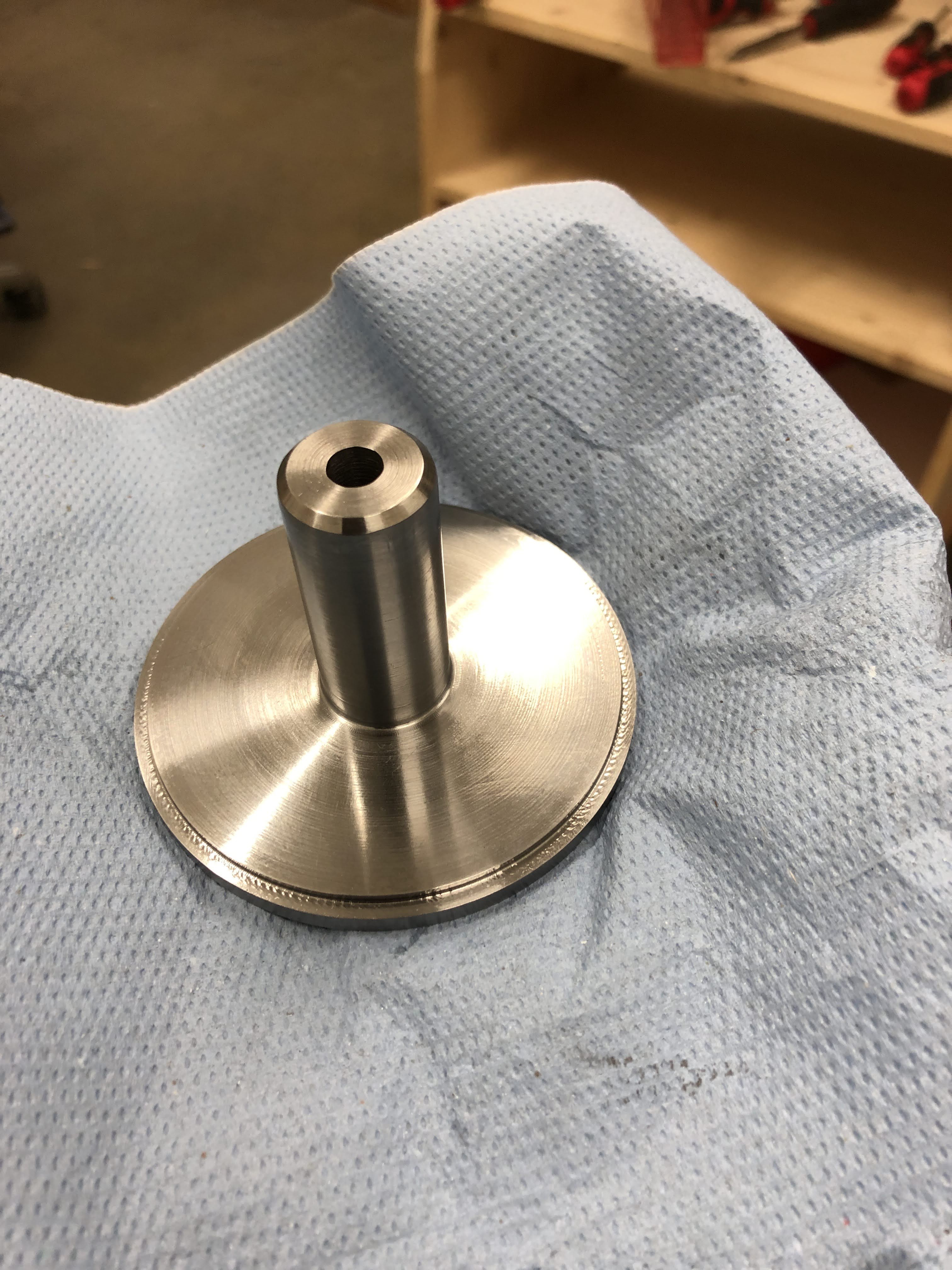
Objective Tip "Final" Part
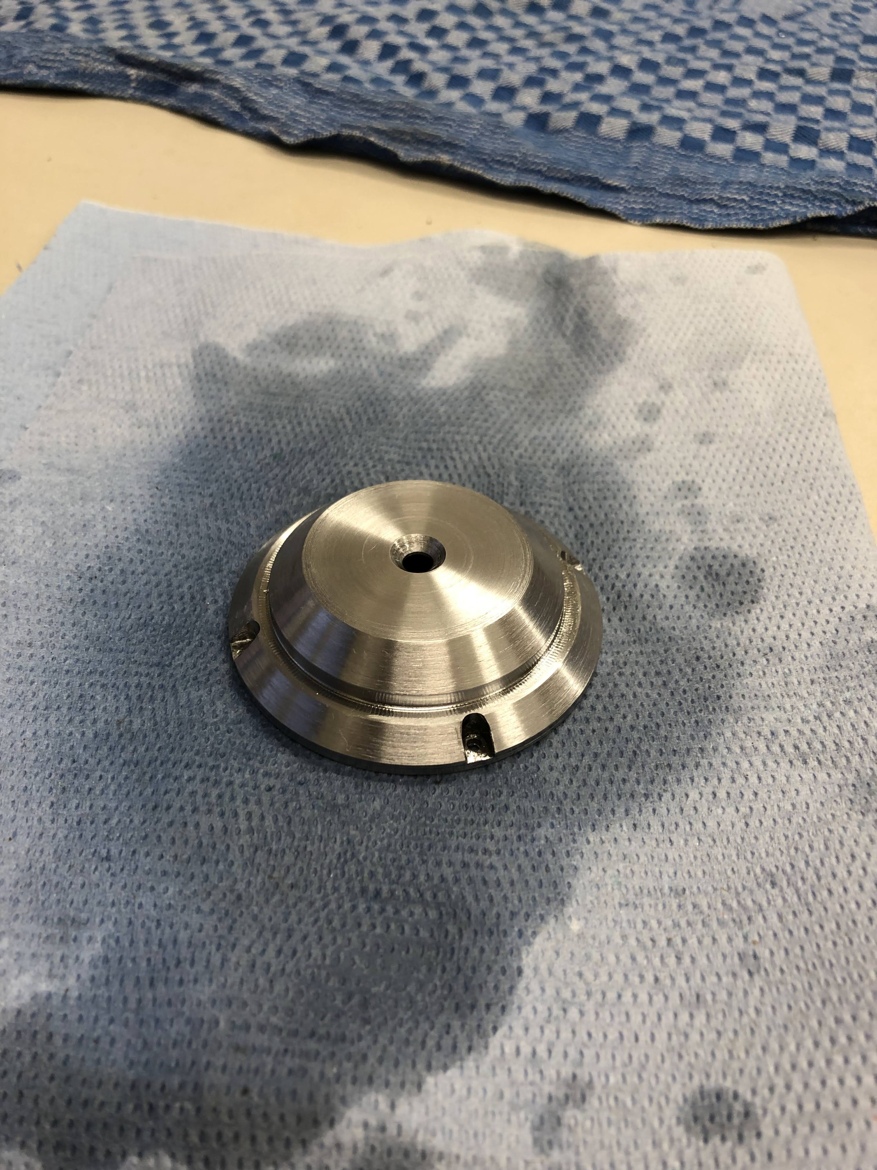
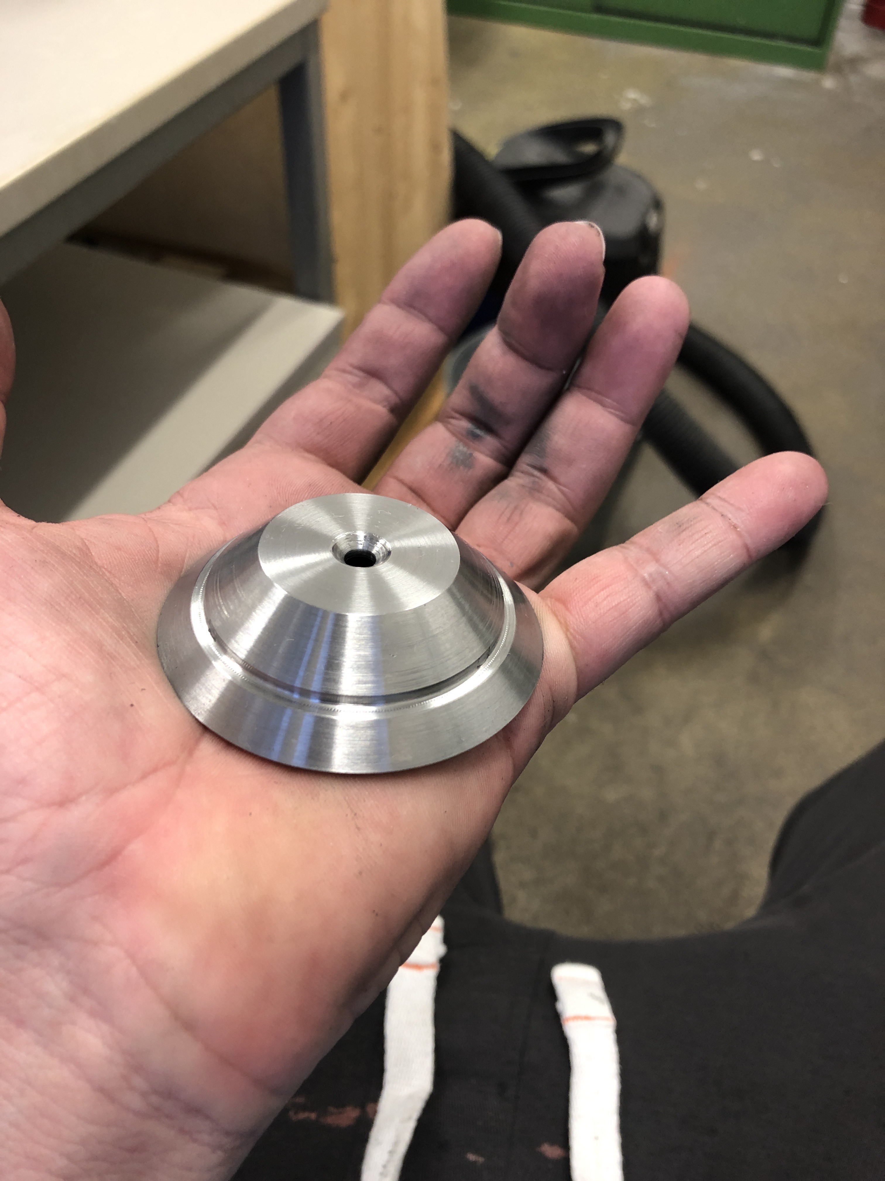
04/07/2022 at 07:28 • 0 commentsSo after my past post I decided to redesign this part.
The knife edge was removed, it was making the part too fragile and I think would difficult the quality on the nickel plating as well.
I had the intention to remove that groove in the middle of the chamfer, but my lathe chuck can't hold the part by the new OD, so I had to keep it. The groove ended up shattering a bit but since is a non functional feature and I smoothed a bit with a stone, so should be fine after the plating.
I will be using the first part to test the nickel plating process.
The part was soaked in WD-40 to protect against oxidation until the nickel plating solution arrives.
![]()
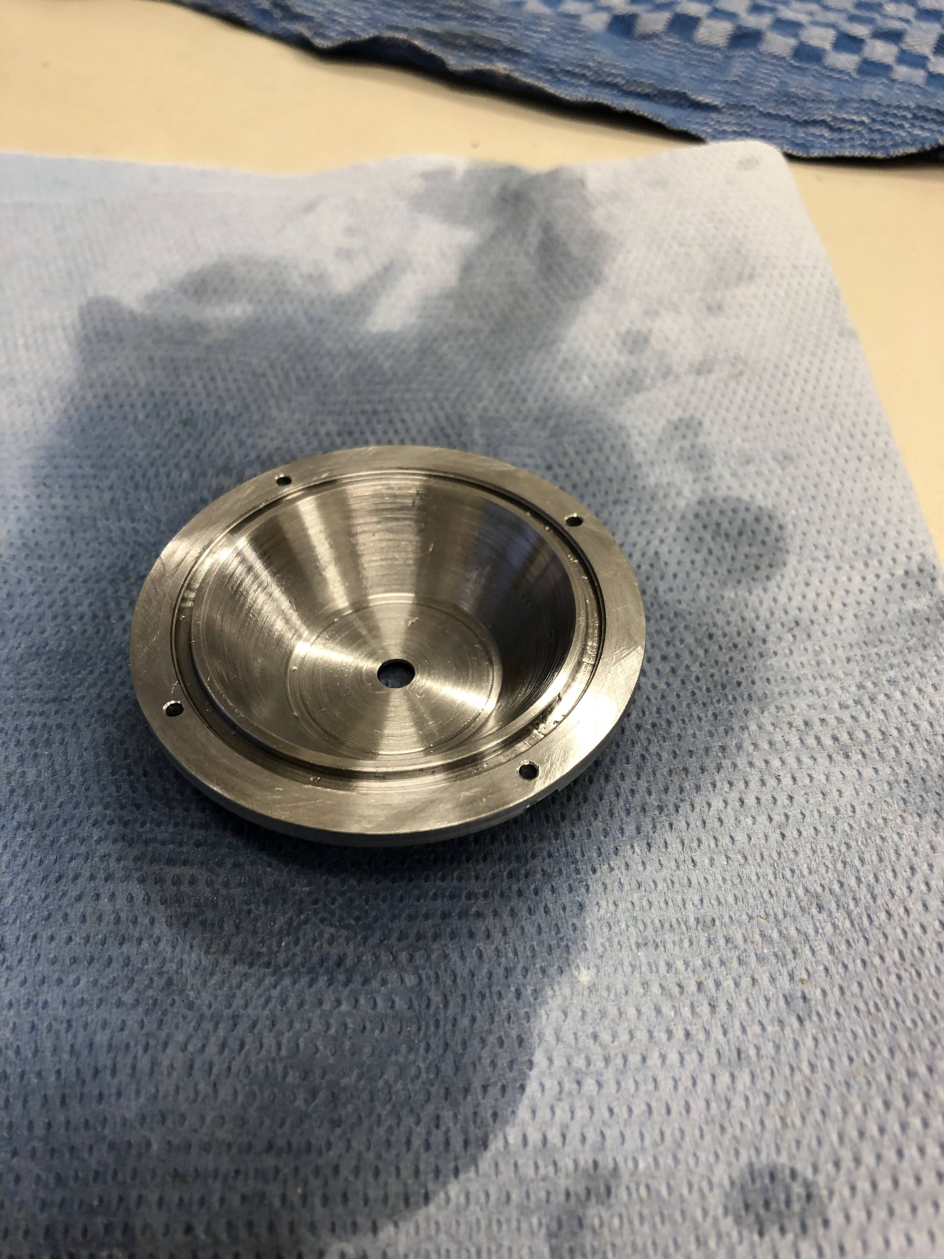
The most critical feature of this part is the O-ring groove. It needs to be as smooth as possible, I was able to get a good finishing sharpening a carbide parting tool that makes the groove in a single pass.
![]()
-
001 Objective Tip machining.
04/01/2022 at 17:37 • 0 commentsObjective External Pole Piece “Tip” is the part 001 in the assembly. It was machined on carbon steel. It is missing the screw holes that will be machines in the sequence. This is more a path finding part. I will probably make some small changes to facilitate the machining process.
-
Mechanical Files Repository
03/30/2022 at 16:27 • 0 commentsHello Everyone.
I am happy to announce I am releasing the fist project files.
The repository is VinisLab/VinisSEM-Mechanical: Vini's Lab Scanning Electron Microscope - Mechanical Design Files (github.com)
I am only publishing the files that are ready for manufacture and I am not planning to do any modifications.
Please watch the repository since I will be doing a lot of uploads there in the next days.
-
One more part being machined
03/13/2022 at 17:54 • 1 commentObjective part being machined
-
Scanning and Capture Card
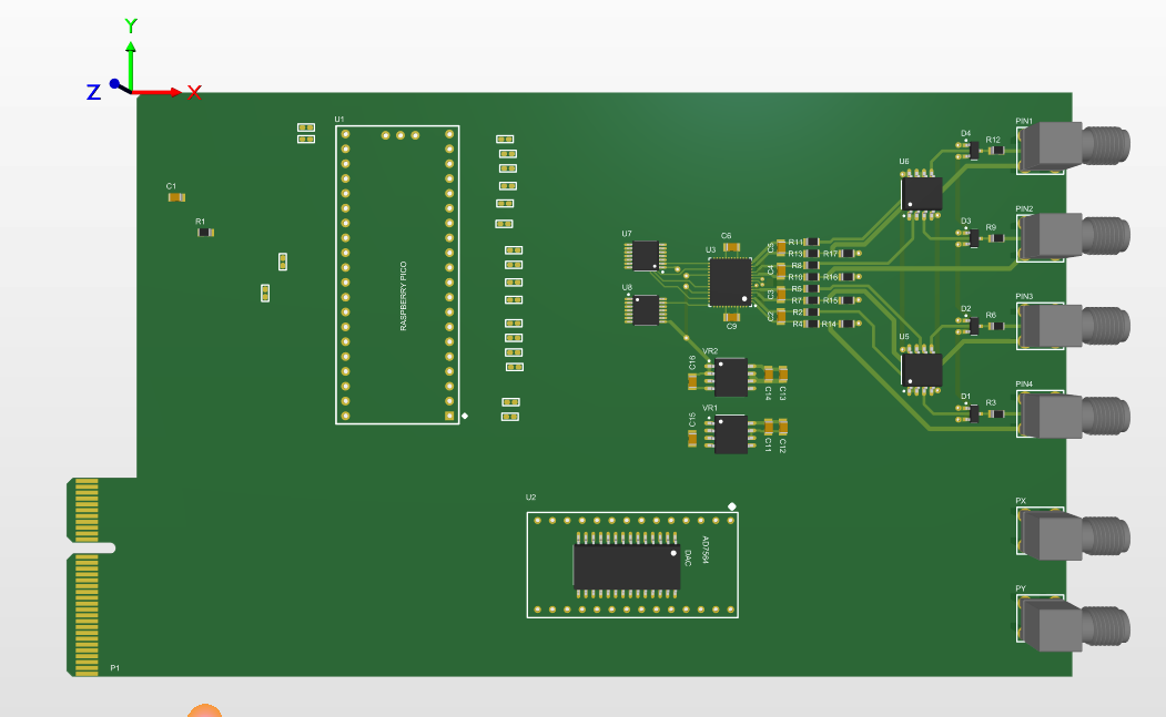
02/28/2022 at 16:54 • 0 commentsCurrently I am working in the Scanning / Capture card.
The scanning and signal capture must be synchronized with each other so they had to be placed in the same card.
The synchronization between DAC and ADC capture happens using the Pi Pico PIO.
It is an amazing peripheral, it can substitute a FPGA in many tasks.
To be able to send data to the computer in high speed I will use the FTDI chip capable of operating in USB 3 mode so I will be able to achieve good resolution at reasonable frame rates operating the instrument in video mode.
The schematic is far from done, I mostly worked on the ADC schematic so far, I will be able to sample 4 channels continuously so multiple detectors can have their data displayed in layers in the software at the same time.
The ADC will expect a signal 0 - 5V on it's buffered inputs coming from the sensors preamp boards.
I will use this acquisition board on future projects as well, so I am making it as general purpose as possible.
I am using a PCIe1X connector to interconnect with my backplane for powering and USB connection.
The backplane will contain a USB hub which will be connected to the host computer.
This is a preview how the PCB layout is going on.
![]()
-
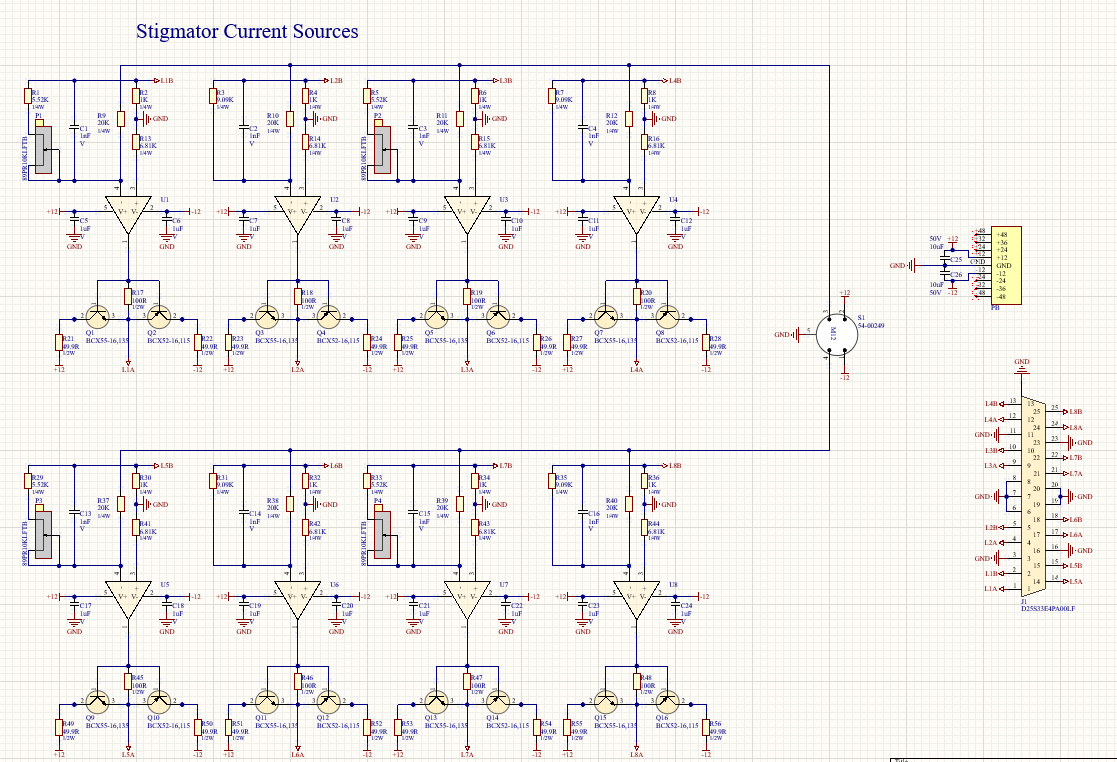
Stigmator Driver Electronics
02/28/2022 at 16:37 • 0 commentsLet's shift a bit now from the mechanics design to the electronics side.
One of the first parts I designed from the electronics was the stigmator drivers and keypad.The reason for that is simple: it is one of the easiest parts :D
All the electronics for the SEM will be housed on a eurorack.
The cards will be split in functional blocks, so the stigmator has it's own card.
![]()
![]()
The first schematic contains the eight independent drivers capable of 500mA of current each to drive the stigmator octopole.
The reference current comes from the keypad which can be adjusted with the potentiometers P2 and P3.
The 555 generates a 0.5Hz signal that is sine waved by the low pass filter and can be selected by S2 and S3 to actuate one of the axis. The schematic is still missing the voltage reference, it only needs to have short term stability since this is an manual adjustment the operator does before imaging the sample.
The Keypad connector is the 5 Pin M12 those industrial connectors are great.
The DB25 connector goes to the SEM column and connects to the stigmator connection PCB via normal braided cable.
-
Machining condenser lenses
02/28/2022 at 16:04 • 0 commentsI decided to machine the condenser lenses in the mini lathe.
It was way harder than I imagined I also had to split the U shaped pole piece into two.
To reach the best surface finish I created a grinder attachment to the lathe and used it to reach final dimension. But this is the diameter limit of the mini lathe I am using machining with carbide inserts.
But the lathe cleaning was the worst part afterwards :D
![]()
![]()
![]()
-
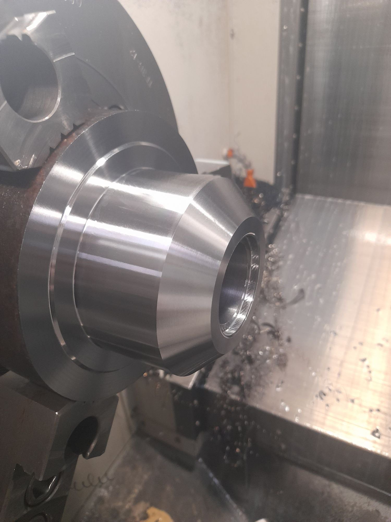
First column part from the CNC Lathe
02/28/2022 at 15:50 • 0 commentsThis is one of the tough parts to machine, a lot of material to remove, some of the features are just for clearance so they don't have the nicest finish, the mating surfaces will be polished.
This was made of carbon steel and will be electro plated.
![]()
![]()
Thanks Ellis Hughes for this awesome job. I am looking forward to receive your parts for finishing and assembly.
-
The Column Design
02/28/2022 at 14:00 • 0 commentsThe first thing I would like to say about the Column is that it was heavily inspired in the old Zeiss DMS9xx series and the reason for that are the following:
- Multiple people I know own SEMs from this series.
- One of them had one taken apart and reversed engineered some of the critical parts and it's dimensions (Thanks Samo).
- One of them reversed engineered the instrument EEPROMs and extracted the condenser current tables (Thanks Felix D.)
- I have access parts of the service manual for this instrument.
Despite the inspiration, most of the parts that are preserved from the original design are the condenser coils air gap and pole pieces dimensions, also the focal length was kept the same between the condenser/aperture.
So let's start from the top of the column going down.
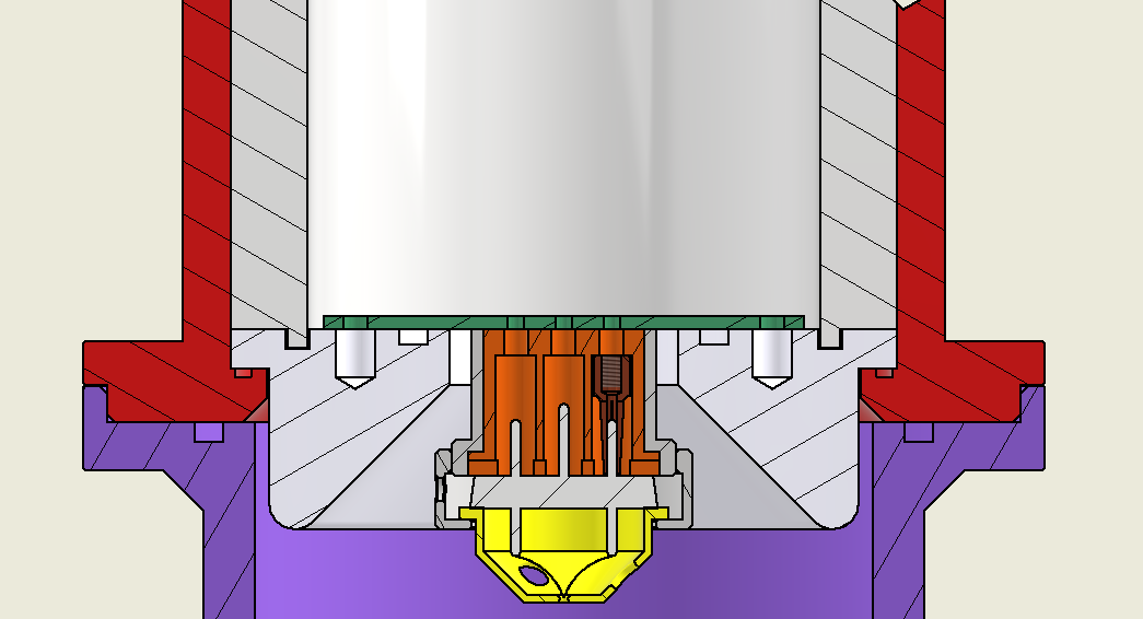
The Cathode (Electron Gun)
![]()
The electron gun design worked around a filament model I have on hands (Thanks Karnathe for the set donation).
I don't know it's model but the filament pins are spaced 12mm between them with a third pin unconnected in the middle for mechanical alignment.
The receptable will be made in the mini lathe from copper, it is composed of the receptable and a threaded pin which is soldered in the green PCB.
The Orange isolator part is machined on PTFE. There are slots sectioning the holes to facilitate trapped gas to release itself from the assembly.
The PCB contains copper planes inside that goes over the viton o-rings to decrease the gas penetration trough the PCB substrate.
The conical isolator around the electron gun assembly is also made of PTFE. everything that gets in contact with the high vacuum when plastic ideally is from PTFE.
The isolator sleeve inside the red shell is made of POM also the top cap will be made of POM.
The red shell is made of aluminum 6061 or whatever I will have on hands, there are not many alu parts on this project, most are carbon steel and some are stainless. The wehnelt is one of the few parts made of stainless.
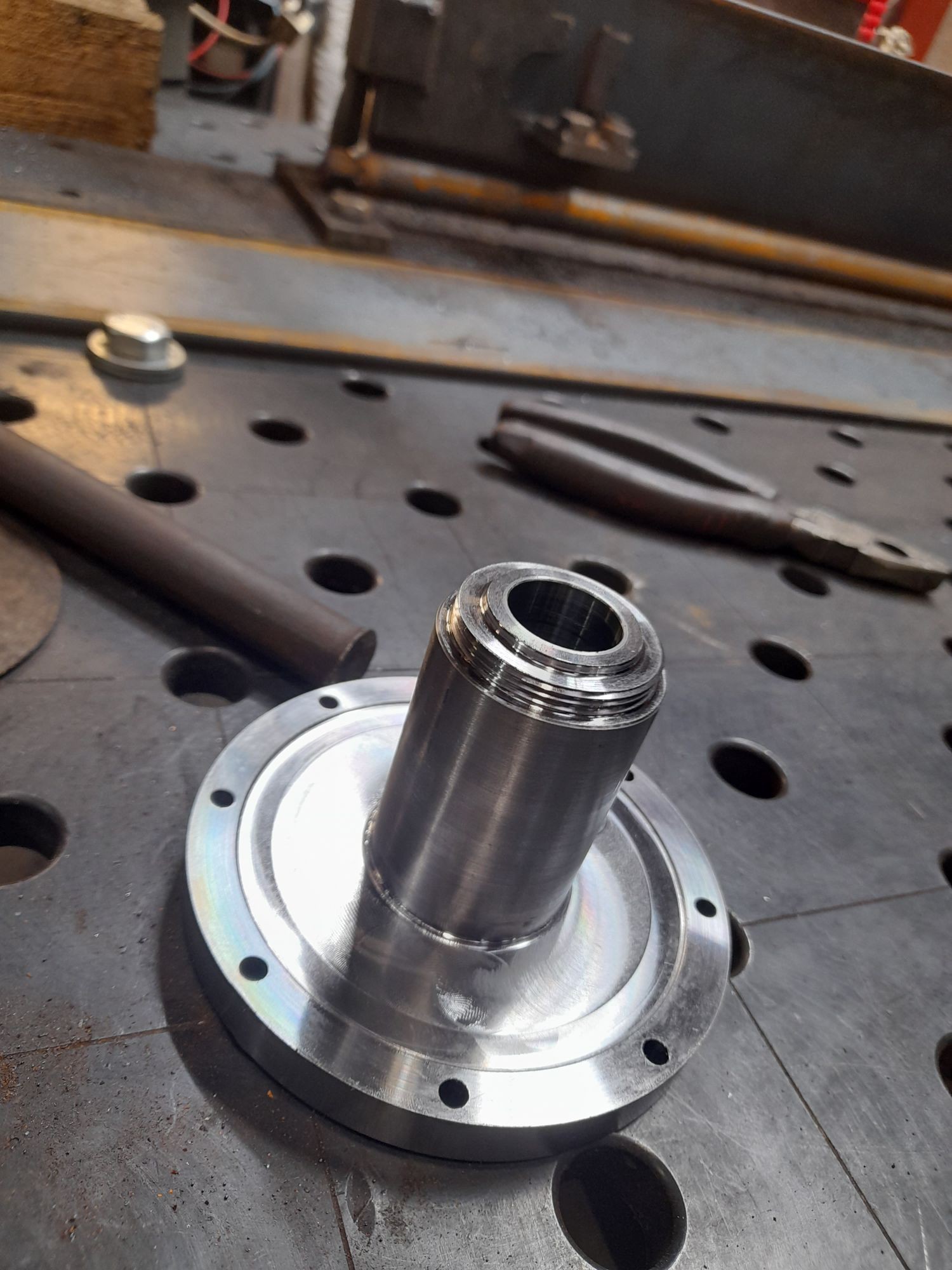
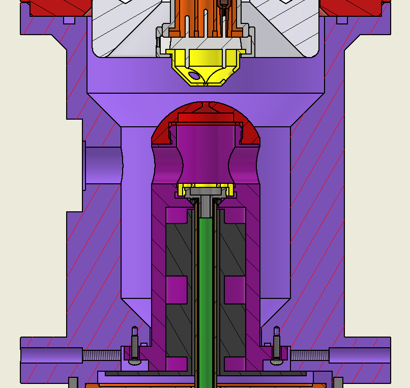
The anode:
![]()
The anode assembly has some of the trickiest parts to machine.
First the anode lens itself, since it is bombarded with electrons I decided to machine with Stainess 316. It's geometry is not easy to machine, but luckily a friend (Thanks Ellis) will make it in a CNC lathe.
It is the only part from the Zeiss design that is dimension accurate surprisely because Zeiss defined all the dimensions for this part on their service manual but I made some slightly changes from the original for easy holding on the lathe.
The intersecting hole bellow the anode lens, perpendicular to the beam axis, is for a future beam blanker. until the instrument is operational I will not bother with it.
The yellow ring is threaded in the anode holder (purple reddish part) and puts pressure in the liner tube (green), there is a o-ring there that seals when the yellow nut is threaded.
The liner tube is the only connection between the electron gun chamber with the aperture chamber.
The black part is where the beam alignment coils will be wound they consist of 2 sets of 4 coils for X and Y alignment. they are necessary because when the filament is changed the tip of the tungsten never gets perfectly aligned with the aperture, those coils function to make this correction.
The purple part is also made of aluminum, I would like to have it done on steel but for manufacturing reasons Alu was chosen.
The anode holder part will be made of Carbon steel, the reason for that is cost, a friend is making this part and he has free carbon steel stock so I am only paying for the service, most of the parts will have almost mirror finish and will be sent to me in oil to not oxidize. I will electroplate and polish them to avoid corrosion. (I know this is controversial, before writing stainless would be better, well when you pay my parts then we can make of stainless :) ).
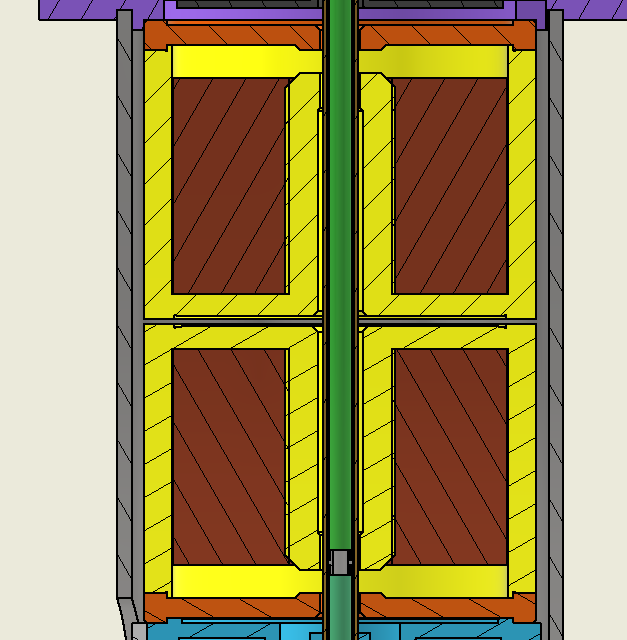
The condenser assembly.
![]()
The condenser lenses are two symmetrical sets.
The original design from Zeiss utilized small condensers with a water cooling pipe to cool the coils.
I decided for a different approach, my coils are much bigger and will use oversized wire gauge to decrease dc resistance and heating. I will also add temperature sensors to compensations on the software side if needed. The pole piece sizing's and air gap was kept as the original Zeiss design, since I don't have the tools to simulate their effect on electron beam and I have the nice current tables for different acceleration voltages from the Zeiss SEM EEPROMs.
The green liner tube contains an interruption as you can see in the image, there is where the second instrument aperture is located, as you can see is very close to the second condense pole piece. The first condenser focuses there. The apertures work as a filter, where only the electrons coming straight pass, everything that is out of axis will hit the aperture giving us a less diffuse electron source and increased resolution.
The aperture selector:
![]()
There are many ways to design the aperture selector, I decided for a linear axis with a machined tip to hold the different apertures, there is a ball bearing that constraints the axis to not rotate and a sprint that keeps the rotate pressed outside, a rotating selector with guide pin will work to set the distance and set screws will be used for fine alignment of the different apertures.
This is a part I am still designing and probably will go trough different iterations. I need to machine and test to find the best way to do.
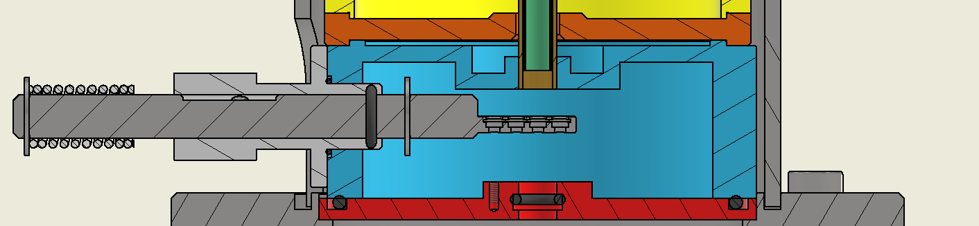
The objective:
![]()
The objective is where most of my machining money goes, it has the biggest parts and I can't possible machine most of them in the mini lathe. The biggest part has 135 mm of diameter, so no way to machine it on a mini lathe.
The outer green and gray parts form the objective focusing lens, the focusing happens around the purple tip and the dark gray part.
The green part in the center contains the imaging and scanning coils, they are potted on epoxy for mechanical rigidity.
The imaging coils works to project an image of the selectable aperture in the sample being scanned and it is used for the whole column alignment.
The scanning coils seat right in the end inside the dark grey part and they do the general sample scanning.
That is for this post. There a lot of details in the mechanical design I am not touching on this post, It is just too much to talk about. This column design was around 6 months or research and path finding.
Now it is time to start to machine parts :)
My Custom Scanning Electron Microscope
This is a scanning electron microscope I am building from scratch from mechanical, electronics and control software.