0. Outline
The basic technical concept for this Geiger counter is copied from biemster's ESP8266 project:
https://hackaday.io/project/12933-esp8266-geiger-counter
This sketchy design has several drawbacks since there is no control loop for the tube HV, an issue that will be addressed here.
I use the Raspberry Pi Pico 1 for prototypes, so connecting the device to the Internet will briefly be discussed yet is beyond the project scope (for the Pico 1 has no IoT capabilities per se).
Connection to a GPS HW in order to display/store CPM values together with a geographical location will be within the project scope.
1. Prototypes
Status as of June, 2024
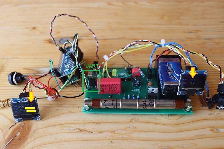
With an SSD1306 0.96'' OLED and a buzzer. Also connected is a Pico-GPS-L76B (GNSS Modul) to determine the geographical location, including an extra Pico because using an extra Pico makes it easier carrying out experiments (so it is not a final concept, obviously).
The Picos communicate thru the UART interface.
Demo video
In a nutshell
On the left OLED you see a CPM values history (13, 14, 15, 10) together with a geographical location (obscured for privacy reasons).
In order to save power, the OLED on the right shows only a bare minimum of data (every pixel consumes energy), and the brightness is diminished. More information farther below.
2. Schematic
The device comprises in essence the MCU board, the boost converter, a power supply network, the HV control loop and of course the Geiger tube itself.
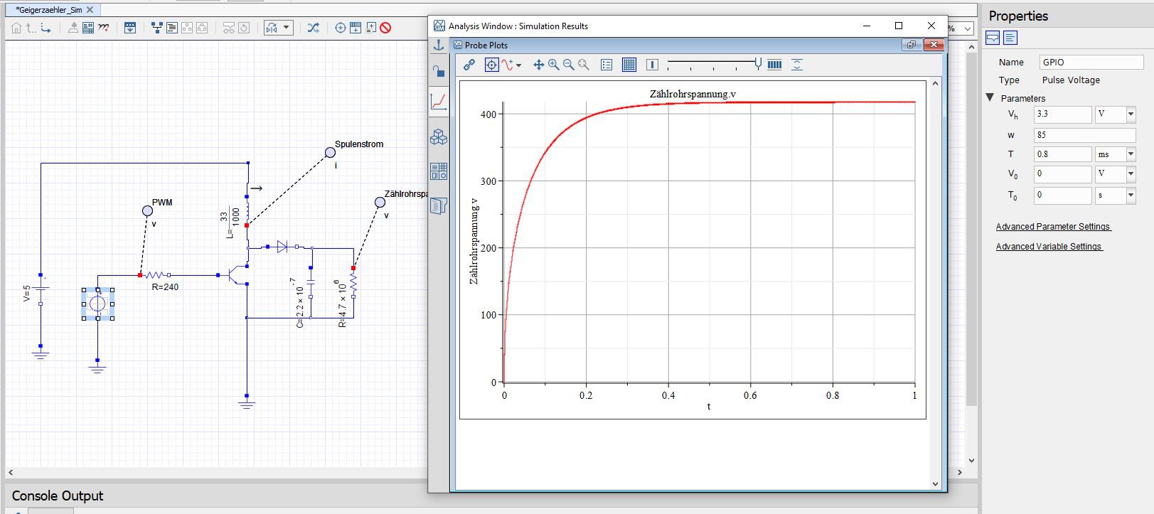
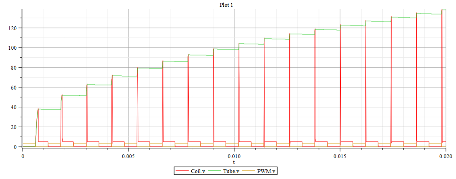
Diode D1 prevents immediate discharge of capacitor C1 and tube voltage is building up quickly. The coil voltage peaks into the double, then triple digits every time the transistor cuts off (see simulation results below).
Upper limit of the PWM frequency is a few kHz: around 2 kHz the HV is starting to drop considerably (edit: with UF4007 not longer the case, see "Note 2").
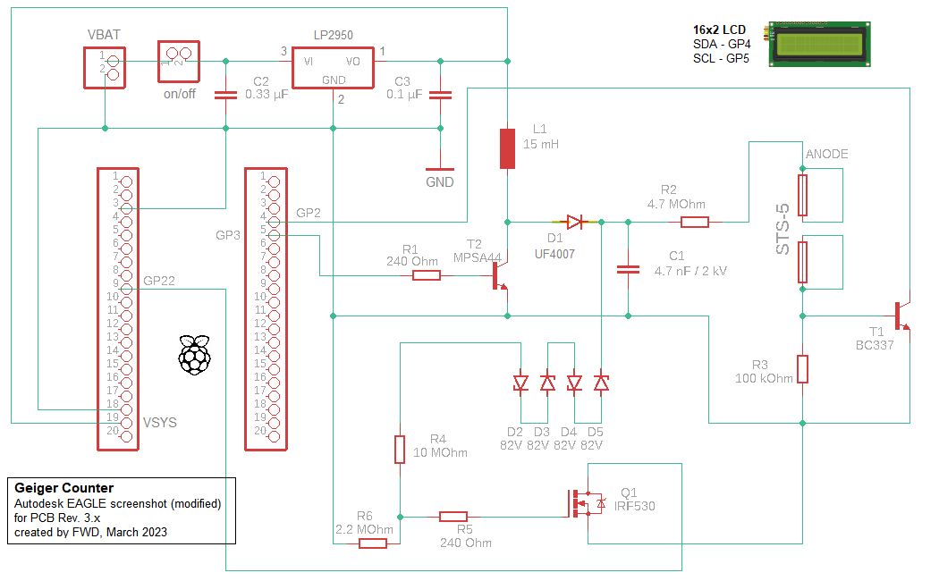
Note 1: values for R1, R5, C2, C3 can be varied (it is mostly irrelevant for the power consumption whether R1 is 240 Ohm or, say, 1 kOhm for I am using a control loop anyway)
Note 2: UF4007 is superior to the originally used 1N4007 (UF4007 better suited for higher frequencies)
Note 3: I've changed the inefficient (but cheap) L7805CV linear voltage regulator to LP2950; C2 isn't really necessary here but doesn't hurt either
Note 4: as a general rule, the anode resistor should be soldered physically close to the tube
3. G-M tube SBM-20 (or STS-5, Cyrillic CTC-5)
With this Soviet Union tube you can detect Beta and Gamma radiation (as with any Geiger tube, you cannot distinguish them), but not Alpha. For the tubes you are seeing on the pictures I paid around 30€ (in 2022, probably more expensive now), including shipment.
Technical data: SBM-20_GER1.pdf (mikrocontroller.net)
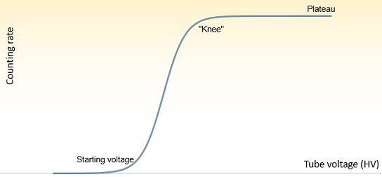
For registering pulses by the counting system proper working conditions have to be established. That means in practical terms generating a tube voltage within the Plateau area.
Beyond the characteristic "Knee" all pulses are (or ought to be) counted. Below the starting voltage, no pulses are counted at all.
4. Emitters, natural radiation and testing
For testing the general viability I use small pieces of Uranium glass (this matter doesn't radiate intensely for obvious reasons).
The natural radiation is detected about 20 CPM (in 49°46xxx' N, 11°12xxx' E) with the current prototypes. There's of course the inherent randomness in the measured data.

Note: for a reasonably accurate realization of the underlying probability distribution there are a lot of samples needed, the given graphs are just for illustration (for seldom events such as radioactive decay, Poisson distribution can be a helpful mathematical model).
5. Program development and display of data
5.1 Conceiving an algorithm from scratch
I use C language for program development. In order to work with it, I had to install the tool chain (the C development system) on my Raspberry Pi.
Necessary for the HV-generation is a PWM with a frequency of e.g. 10 kHz and a duty cycle of e.g. 60% (output here on GP3, see paragraph 5) - those are empirical parameters.
As we have an MCU connected there are several ways how to handle measurement data.
Triggering IRQs and counting them (here on GP2) is one pragmatic method, for a pulse (gas discharge, i.e. counting event) has a duration of about 0.3 ms. Problems may arise with high counting rates for the interrupt handler might be unable to deal with them properly (up to about 500 CPM, a counting rate I'm able to generate with my emitters, everything seems alright).
5.2 Displays
For a more sophisticated display of data (statistical calculations, graphs etc.) than just flashing LEDs or triggering a buzzer, an off-the-shelf display can be used. The Pico SDK makes common types of displays, e.g. a 16x2 LCD or a SSD1306 OLED, fairly easy to use - keeping in mind that an LCD/OLED connected to the I2C bus may or may not have its own pull-up resistors.
LCDs consume too much power for my taste, so I don't use them any more (though they look aesthetic).
With the OLED, a compromise has to be found between fancy display of data and power consumption. More characters i.e. activated pixels and more contrast equal higher consumption.
5.3 CPM (Counts Per Minute) calculation
As for any purely statistical information (such as radioactivity) the question is what to do with cumulated data and in which manner present it to the user (on a display or other devices).
A straightforward way would be composing an arithmetic mean of extrapolated CPM values over a fixed time frame. For instance: 2s measurement, extrapolation, then take 5 extrapolated values and generate a mean value.
The most recent value replaces the oldest value (FIFO), what is basically a ringbuffer principle.
for (int i=0; i < ringbuffer_elements; i++)
     {
          sum += ringbuffer[i];
     }
mean = sum/ringbuffer_elements;
6. Simulation
Though a boost converter is neither a new concept nor very original (element values can be copied from other projects), it may be worthwhile to play around with a simulation (screenshots of the tool "MapleSim" below).
Note the exponential function build-up of the tube voltage.
7. EMC
Air wirings act like antennae and must be avoided for more advanced prototypes. Ground planes for PCBs are arguably a good idea (minimizing EMI/RFI emissions), but they have to have a sound design (creeping current may be the more significant problem).
8. IoT (Internet of Things)
As mentioned above, connecting the device to the internet goes beyond the project scope for the Pico 1 lacks WiFi. But it is not hard to pull that off at all for there exist comprehensive solutions already (e.g. WiFi (ESP8266, Pico W) or BLE (RN4870)).
IoT Geiger Counter w/ RN4870 BLE Module | Hackaday.io
9. Power consumption
Optimizing the device's power consumption is a project in its own right, and goes beyond the project scope as well.
A self-evident and quick ad-hoc measure is reducing the system clock of the Pico, what is easy to do via SW (memory-mapped registers, that is) - very low system clocks conjure new problems with the interfaces however.
Another measure can be using different linear reglators.
Current prototypes (SW-V 3.92, HW 3.x) consume overall approximately 6 mA.
10. Costs
I have/had to spend around 50€ for one prototype, excluding GPS module (Tube 30€, LCD/OLED 10€, buzzer 2€, PCB and electronic components 5€-10€ depending on the distributor).
11. Misc
The background photo of this project page shows a former Uranium mine in Příbram, Czech Republic.
 Florian Wilhelm Dirnberger