 Florian Wilhelm Dirnberger
HW Rev. 2.x
Simple HV measure arrangement: consisting of four 82V Zener diodes, one 10 MOhm and one 2.2 MOhm resistor (series connection). These are parallel to the tube Anode and GND.
The Voltmeter is parallel to the 2.2 MOhm resistor.
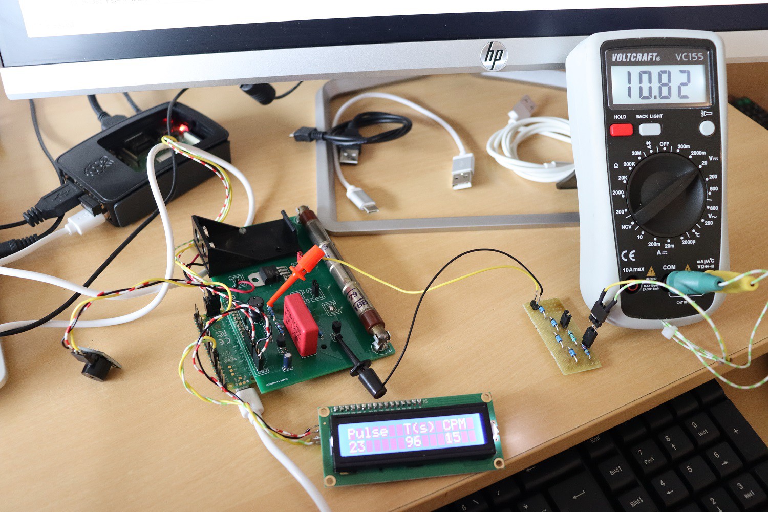
On the picture you see a voltage of some 11V, what means the HV amounts in this case to:
HVtube = 11 + (11/2.2)*10 + 4*82 = 390V
(the voltage is higher actually because the Voltmeter has an internal resistance in the 10 MOhm range so the measured value is slightly off)
Varying the PWM parameters in the SW would lead to higher and lower voltages, respectively.
This assembly could be the basis for a control loop design (edit: realized).
Discussions
Become a Hackaday.io Member
Create an account to leave a comment. Already have an account? Log In.
That's a great way to measure the HV, I did not see this before. I never got around to building something that can actually measure this on my board, this circuit is now high on my TODO list! thanks!
Are you sure? yes | no
Thanks for your reply biemster, I appreciate it!
Are you sure? yes | no