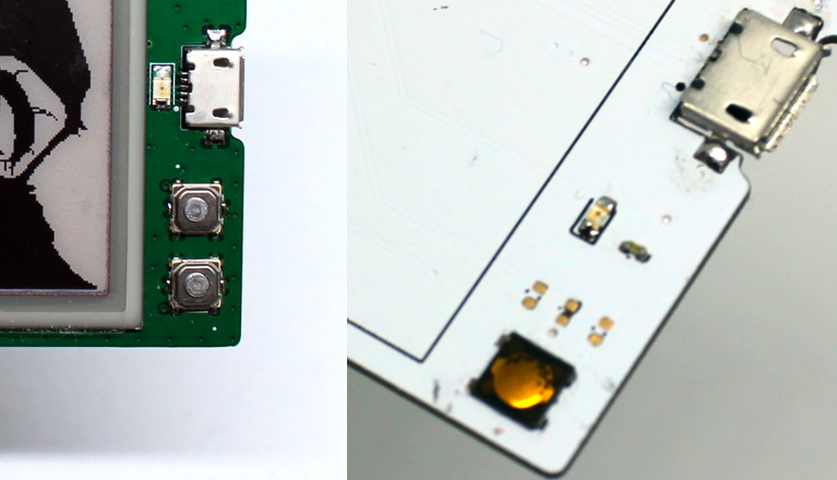
So for this log I am going to write about the changes I have made for the second version of the board.
Lets start with the front.

- The most obvious thing is that we went to green color.
- Add a second button. This will help with navigation.
- Moved the LED next to the USB. Also I chose a bigger package. This way I can put it in line with port and have the D+/D- lines pass between the pads for the LED.
- I chose e different style of buttons. The one I had in the begging was EVQ-P6PB35 from Panasonic. It was very slim and small. Too slim and too small. Very hard to push. The ones I got next had a little stem, which improved the experience. And have some ingress protection.
- I had some resistors and caps on the front for the button debouncing and for the LED. They went to the back of the board.

Lets move to the other side.

- Fix the ordering of the pins on the flat flax connector.
- Connected the ground pin on it as well.
- Put the correct transistor footprint.
- Removed the temp sensor for the e-paper display. It is not needed.
- Changed the LDO because the BGA one was pain to solder.
- Moved the debug header so it does not interfere with the radio.
Removed the RST pin on the debug header and connected it to the second button. It can be configured as a GPIO.(this is not done on this revision)- Added that low frequency crystal I deleted on the first version.
- Add a fuel gauge for the battery.
- I removed the battery over current protection IC. It was a bad choice from the begging.
- Changed the trace that is going to the antenna. Now it has the correct impedance.
- Moved some components around to have cleaner look.
More or less that were the changes. Thank you for reading my logs.
Cheers,
Mitko
 Dimitar
Discussions
Become a Hackaday.io Member
Create an account to leave a comment. Already have an account? Log In.