Tools
As I said in the project update, I couldn't get my initial design to work. I have an oscilloscope and a very cheap logic analyzer but using these tools is cumbersome and finicky. They can only measure what goes to the pins, not what's happening internally. Strict timing control is hard to do and measure. Moving physical devices and wiring around is time consuming and has the potential to introduce new bugs each time you do it.
What I needed was a way to see signals at the gate level, a way to synchronize signals, and a way to quickly swap gates in and out without moving a bunch of wires. So I moved to software.
Digital
For now, I am very much enjoying the interactive nature of Digital, an open source logic circuit simulator by H. Neemann. With it, I can start to slowly build out my circuit, play with it, and see what happens.
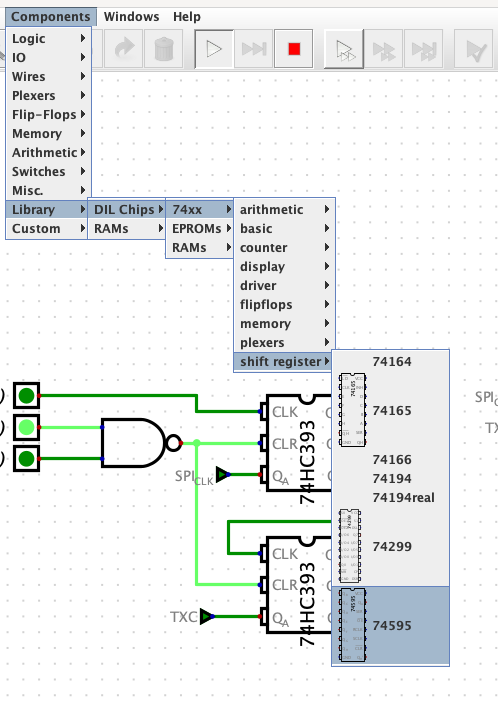
Out of the box, Digital also has a number of simulated TTL circuits!

Here you can see both the '165 and the '595 from the data register. It doesn't, however, have everything. Some devices, like the '393, are missing. What to do?
If You Build It, They Will Come
Digital lets you model things at the gate level, so let's add a '393 to our library. Where do we start? With the datasheet, of course! Many (maybe even most?) datasheets include a logic diagram that gives you the function of the chip. Here's the logic diagram for the '393:

Here you can see the signals and basic parts for a single counter (there are 2 in the package): an active-high CLR, a clock on the negative edge, and 4 T (toggle) flip-flops. Let's use Digital to recreate this circuit. We'll start with 4 T flip-flops and a clock:

Digital has built in T flip-flops. This is hooked up like it appears in the datasheet, but what about T? In a T flip-flop, T acts like an enable signal. When high, toggling is enabled and when low toggling is disabled. The '393 has no enable/disable signal so we'll tie this high. Now let's simulate this:

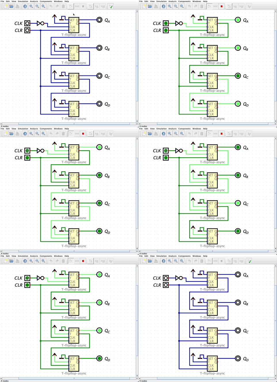
That doesn't look right, it looks like it's counting down not up! And that's because when you toggle the clock, Qa goes high, which is the clock for Qb so it goes high, which is the clock for Qc, etc. How do we fix this? By using the inverted outputs as the clock for the next stage:

There are still 2 problems here, though. The first is easy to fix: the '393 clocks on the negative edge, while this circuit is clocking on the positive edge. Simply inverting the clock signal will give us the desired result.
The 2nd problem is tougher. When this circuit starts up, you can see random values on all the outputs. Toggling the clock counts up but not from zero. We need the ability to reset all the flip-flops.
Unfortunately, Digital does not have a set/resettable T flip-flop. That's ok, though, we can make our own. Digital does have a built-in D flip-flop with set/reset. So we'll use this and convert it to a T flip-flop:

Next, we'll replace the built-in T flip-flops with our resettable T flip-flop, hook up the CLR line, and correct our clock:

And there you have it! We now have a functioning '393 to use in a larger circuit.
But why go to all this trouble? To validate the SPI Master, I previously used a built-in binary counter, but its characteristics were not like the '393 (positive clock edge, synchronous clear, etc.) It's important to simulate actual hardware as closely as possible when translating to the real world.
 Nate Rivard
Discussions
Become a Hackaday.io Member
Create an account to leave a comment. Already have an account? Log In.