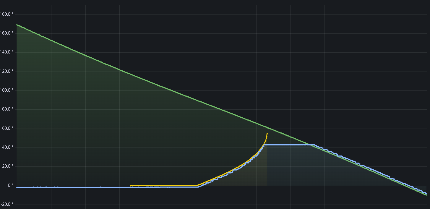
When the sun is in the extreme positions one panel can generate shadows in the adjacent one.
For this reason I added a logic that calculates the shadow incidence based on our assembly and sun position.
On this Grafana chart you can observe the green light being the sun position referenced to the installation position, this angle is converted from the sun's azimuth and elevation.
The yellow light is the shadow compensation curve.
The plateau observed between the two different curves in the blue line is caused because the travel limit.
The blue line tracks with 2 degrees of error the sun position, this data comes directly from the accelerometer and is used by the motion control.
The result is quite good since the motor is not using an inverter and only uses relays to start and stop.

 Vini's Lab
Discussions
Become a Hackaday.io Member
Create an account to leave a comment. Already have an account? Log In.