I tried to put my effort to program a single smd Arduino chip without soldering. But I get failed, and now I am here to explain the concept I am thinking. But let’s first discuss the problem and something about Arduino smd chip. And I think it is right title "Wireless Programming" there is no any wires direct wires included in programming.
Arduino smd chip:
Arduino is a basic AVR RISC based microcontroller. These microcontrollers are available all over the world and famous for good projects (not only basic, but the life changing one’s). Arduino platform is open source and there are heaps of codes and programs available in free. So, anyone can design their own board and create electronics stuff.
The main microcontroller behind this is ATMEGA328P (8-Bit MCU). By the way, I also made some clones boards – you can see them from here.
So Atmega328p is available in mostly two packages (DIP and SMD). DIP version is too much big and heavy for the projects like – flight controllers and drones. I am focusing on SMD version of this chip.
Problem:
Basically, I want to program the IC without soldering. Because once the program got loaded in the Ic I can sell the programmed ICs. The new without soldered and bootloader burnt one. The bootloader creates a lot of problems in those clone Arduino boards. Yet, I have the solution for bootloader but I want to program without soldering. And I am trying this with the help of JLCPCB, offering 5 pcs top quality PCB in just $2.
They are providing amazing SMT assembly Service in very cheap prices. This may be deal to Grab for you guys. Sign-up using this link and get 4 coupons worth $27 for your PCB order.
Parameters:
Nowadays this microcontroller is made by Microchip and the package includes these parameters as mentioned in datasheet
The chip has 32 pins and the total thickness(diameter) of chip is around 1.05mm (without including pins). The thickness of pin metal is 0.15mm and which make the total of 1.20mm.
So, this is cleared from the datasheet that pins are mounted beneath of the chip, not in middle and not on the top.
There is around 0.80mm clearance between each pin of the ic and Diameter of each pin is 0.40(normally). All the other parameters are mentioned, so that you can make an idea.
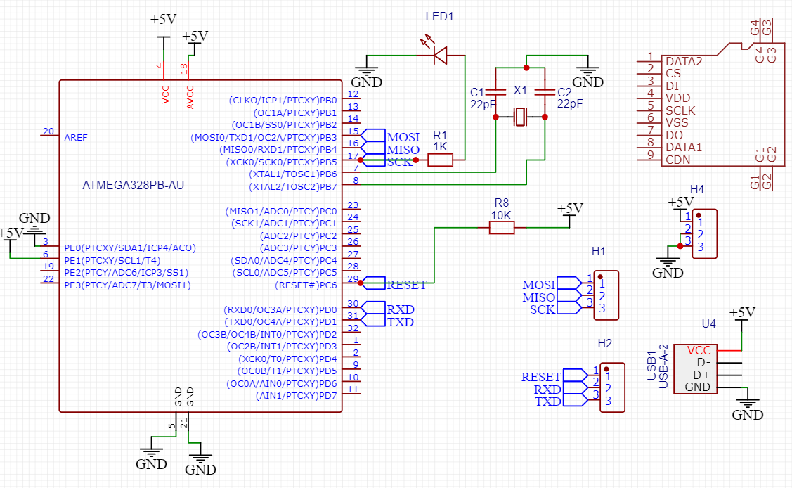
Testing Circuit:

My idea:
I am thinking that, why not to program this chip over the PCB pad. Because there is around 0.15mm between the pins and bottom surface. So, we can press the chip on pcb copper pad, which will make the electrical contracts between the pin and surface. Then we can program it simply.

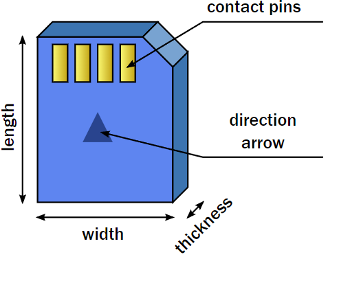
Then I think about Sd cards and sim slots and that blew my mind. The length* width is (15*11 respectively) and thickness is around 1mm. But there is push lock/unlock option is available. Also, the SIM card technology is using the quite similar tech behind locking system.
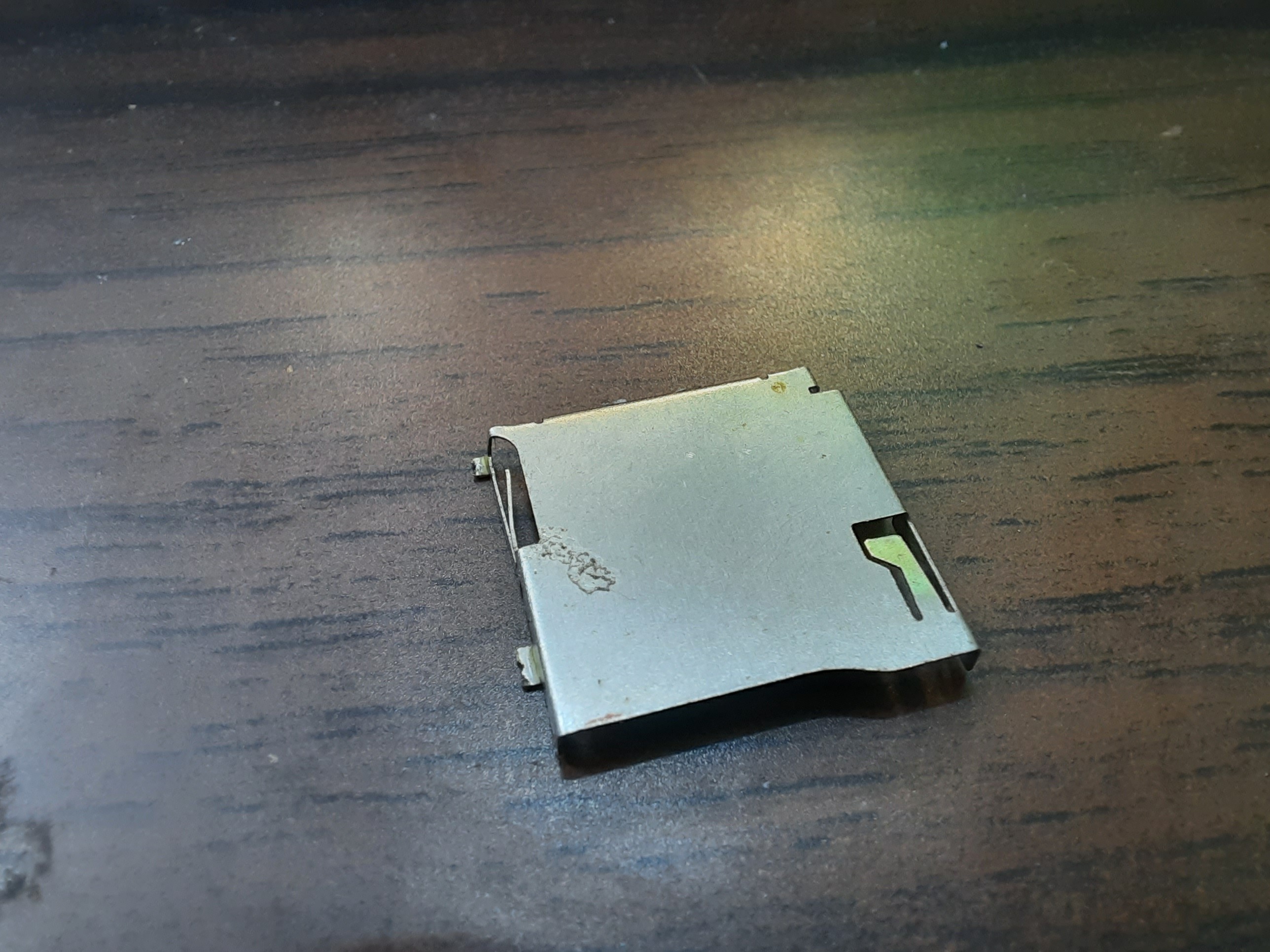
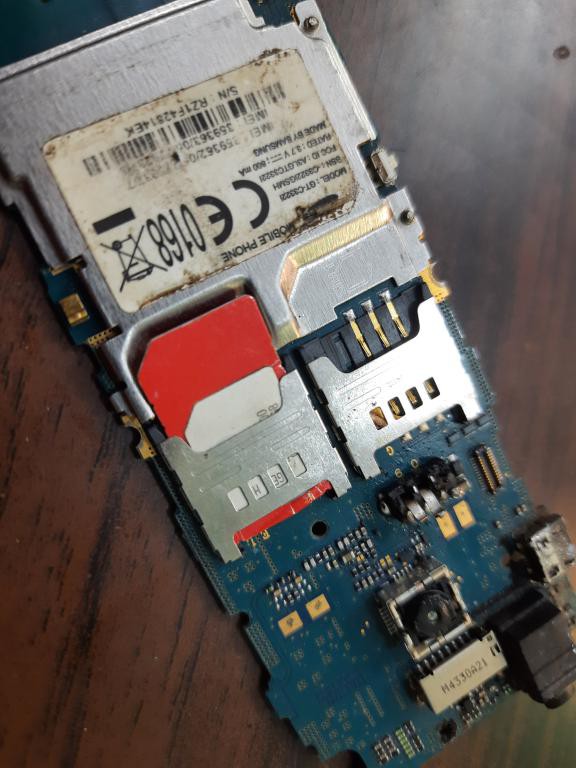
So, I broke my old mobile and MP3 in the search of some golden science behind this. Finally, I decide to make a PCB layout with Sd card slot.
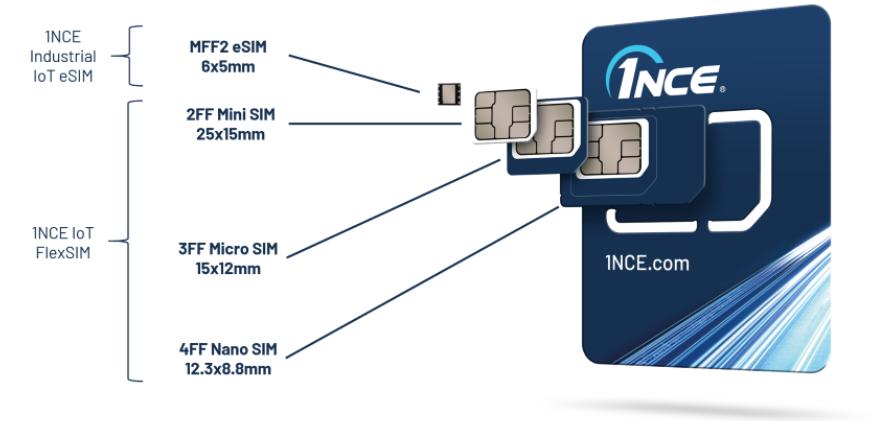
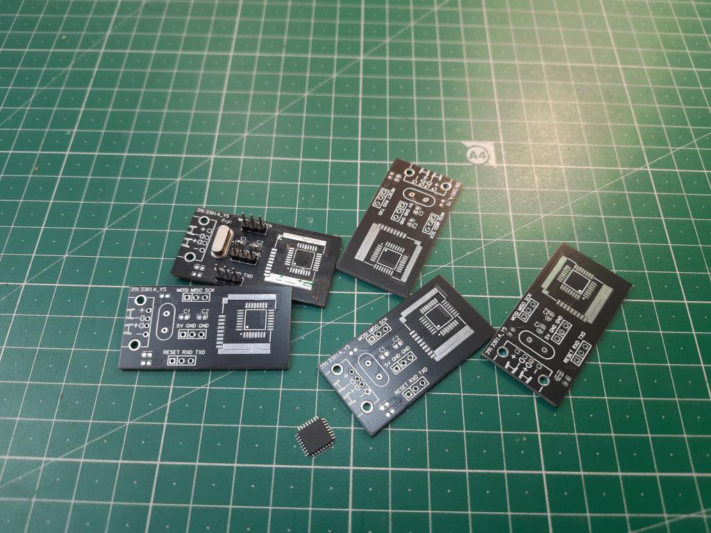
So that we can Insert the chip inside and adjust the connection between the copper pads. Here is my pcb layout for this. The crystal oscillator is to give proper clock while programming. I use Pin headers for programming and Usb to give power to the circuit.
PCB manufacturing:
Ordering process:
My link is here for you, Get big discount coupons on your Very first order. Sign-up Now on JLCPCB. And try services like- prototype PCB, Stencils, SMT assembly and 3D-Printing.
Working On idea:
First, I mount all the components on PCB and tried one of these 5 board with soldering the chip on them. And this is working well and now it’s time to program without soldering.
The PCB has power led which is obviously indication of power and the LED will stop glowing if any short circuit happen in the circuit. The programming system is directly attached to my personal laptop, And I am in...
Read more » ElectroBoy


 Lithium ION
 Sagar 001
 Simon
Simon
I bought a ~$15 qfp-32 zif socket so I can pre-flash bootloaders onto blank atmega328p chips. Works really well when used in conjunction with a standalone bootloader burner pcb I designed, no computer required!