 Ghani Lawal
- This is a block diagram of how the music visualizer operates
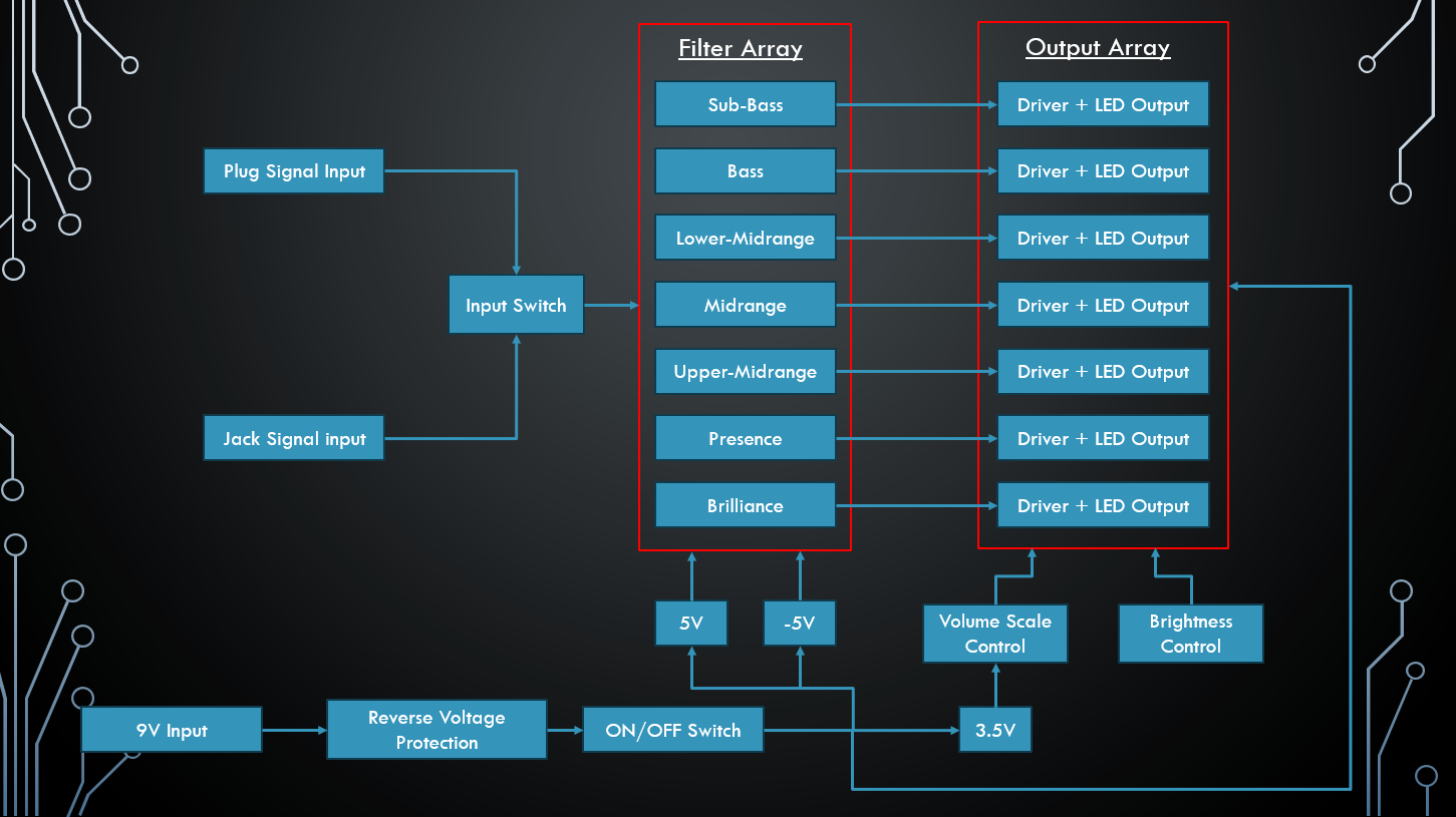
- The entire system is powered by 9V
- A pmos transistor is placed between the DC power jack and the wrest of the circuit to protect it from negative voltages
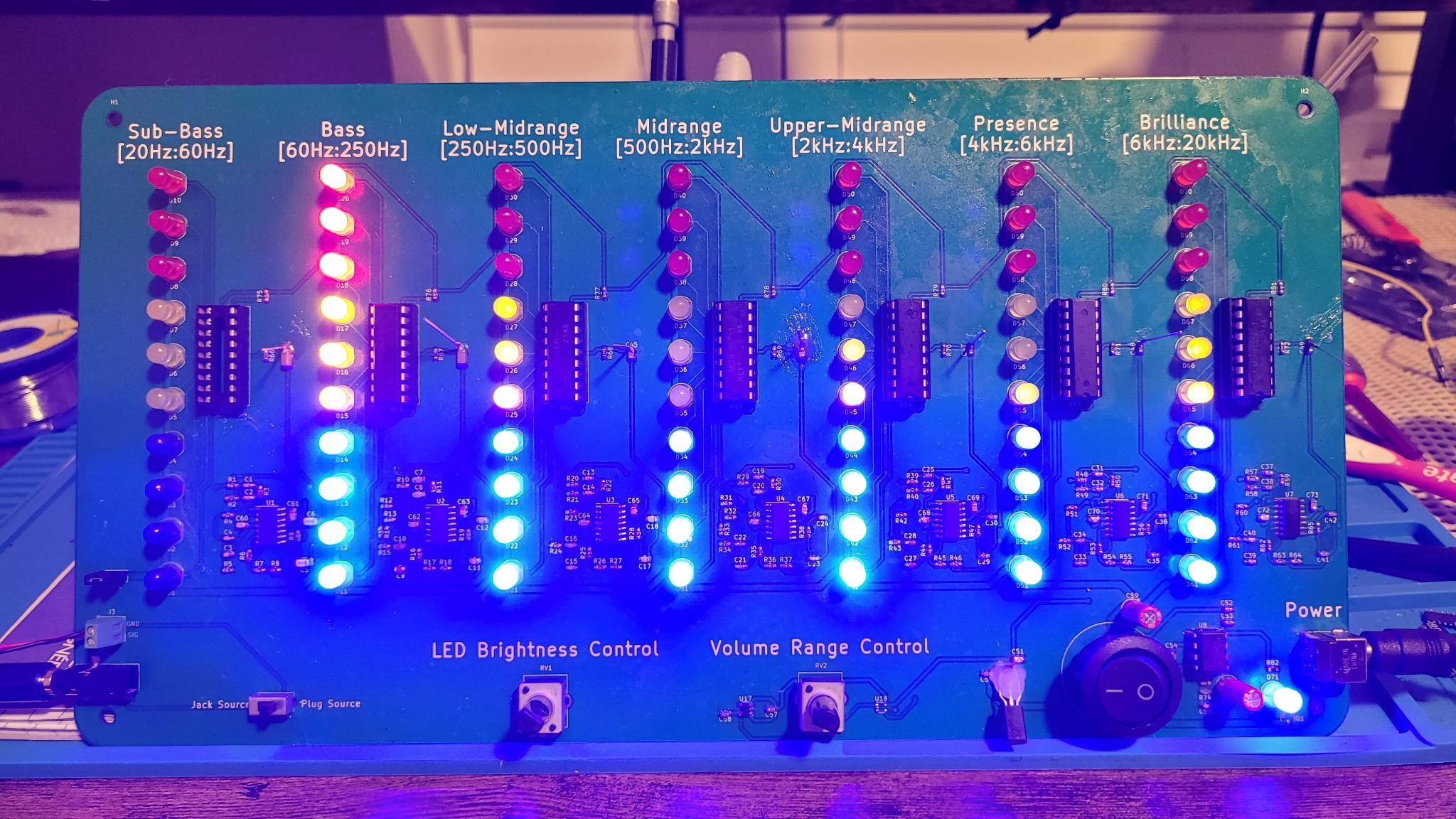
- When the device is switched on, a blue indicator LED will glow, confirming that the board is receiving power
- The device takes in a mono-stereo audio signal from either a jack or a plug, depending on the position of the input switch, and is fed to the Filter Array
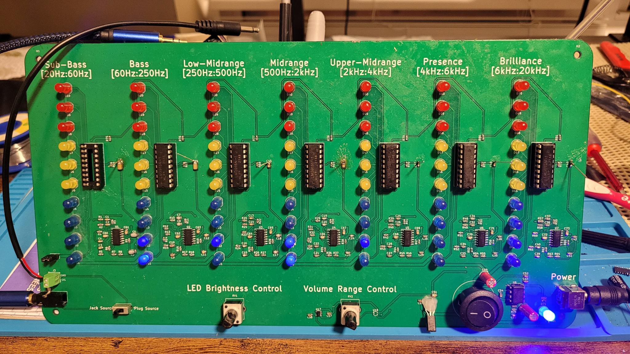
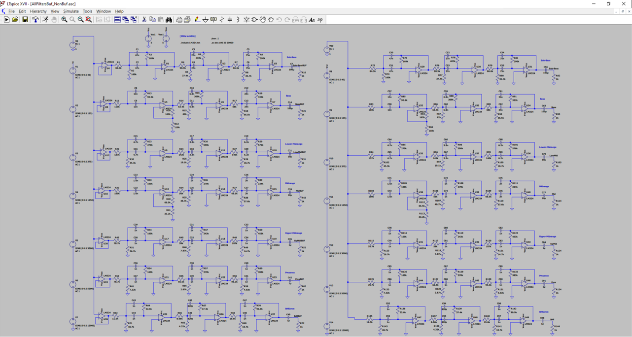
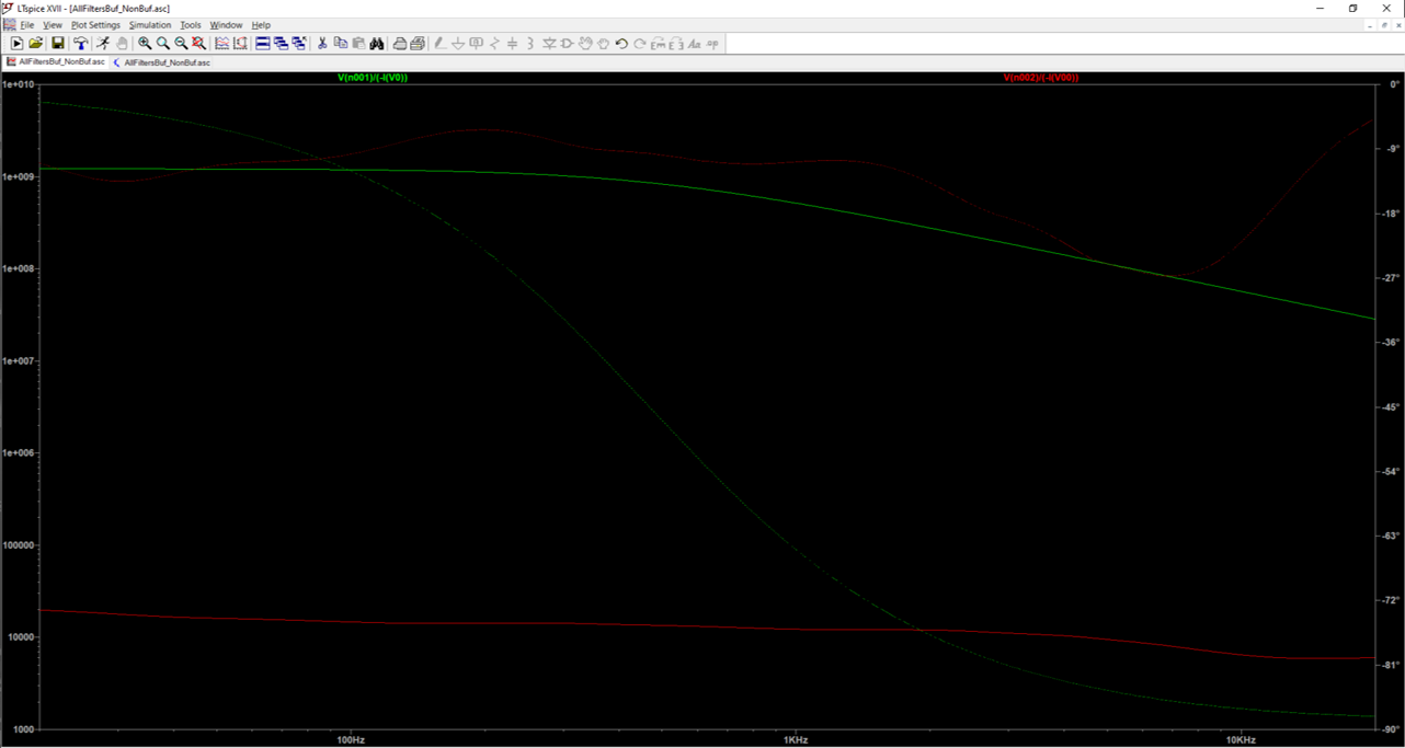
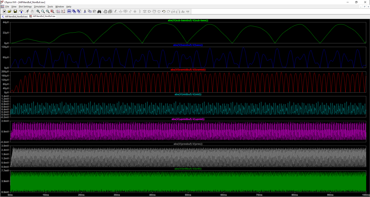
- The Filter Array:
- Is composed of seven 6th degree bandpass filters
- Sub-Bass - [20Hz : 60Hz]
- Bass - [60Hz : 250Hz]
- Lower-Midrange - [250Hz : 500Hz]
- Midrange - [500Hz : 2kHz]
- Upper-Midrange - [2kHz : 4kHz]
- Presence - [4kHz : 6kHz]
- Brilliance - [6kHz : 20kHz]
- Is powered by +5V and -5V
- Can accept analog signals with a magnitude of up to 3.5V without clipping
- Once each filter is finished processing the input analog filter, they sound their outputs to the output array
- Is composed of seven 6th degree bandpass filters
- The Output Array:
- Is composed of seven LED drivers, each of which have 10 LEDs that they drive logarithmically
- Each driver receives an input from its associated bandpass filter, based on the magnitude of the received signal, it will pass particular amount current through a certain number of LEDs
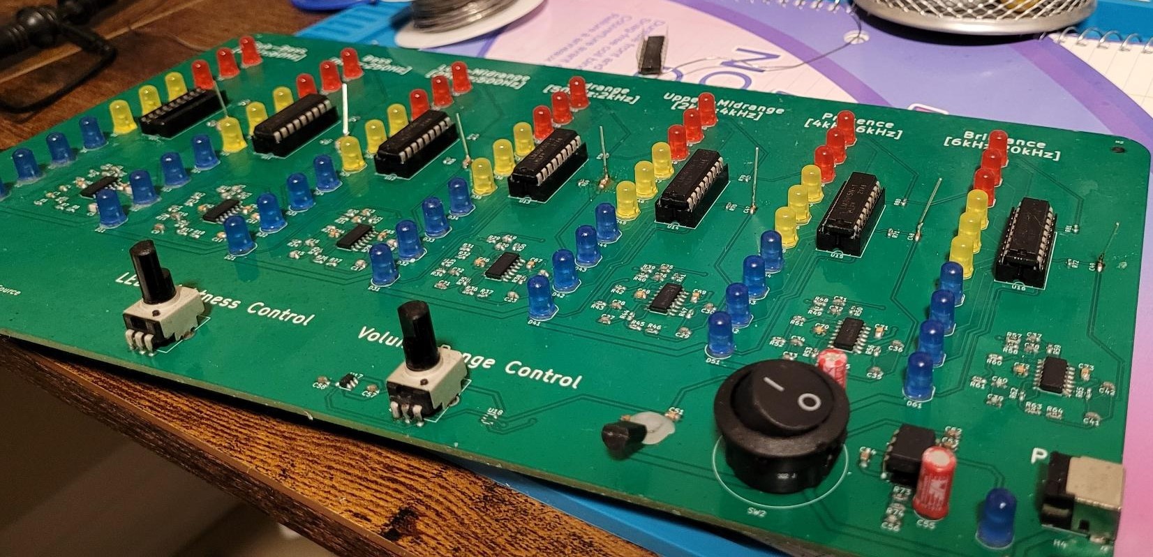
- Volume Scale Control:
- An HMI interface, by turning the potentiometer, a user can change the reference voltage (from 0V to 3.5V) that the LED driver uses to decide how many LEDs should be activated
- Brightness Control:
- An HMI interface, by turning the potentiometer, a user can change how much current the LED drivers all to pass in the LEDs when they are activated, from 0mA to 18mA


 Sagar 001
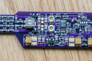
 Bud Bennett
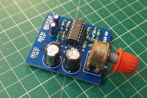
 ElectroBoy
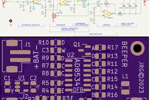
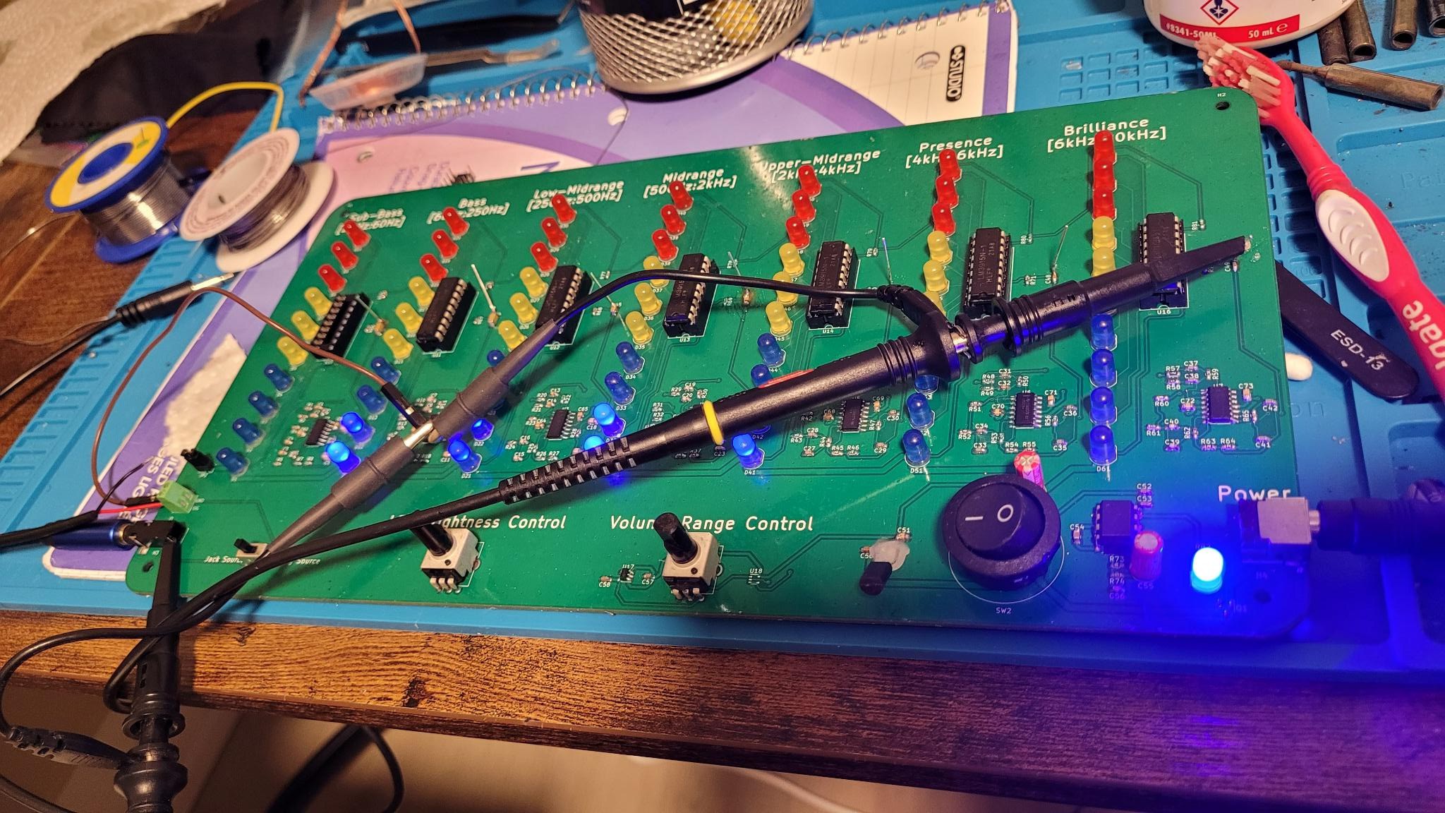
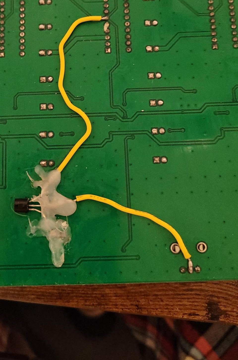
ahahah yeah I underestimated how hard they would be to solder