 Michael Gardi
I created a template to cut out the "in"side panel pieces for the MCM/70
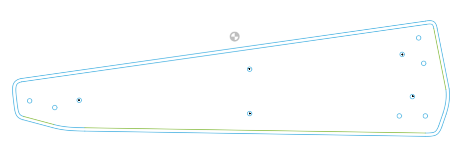
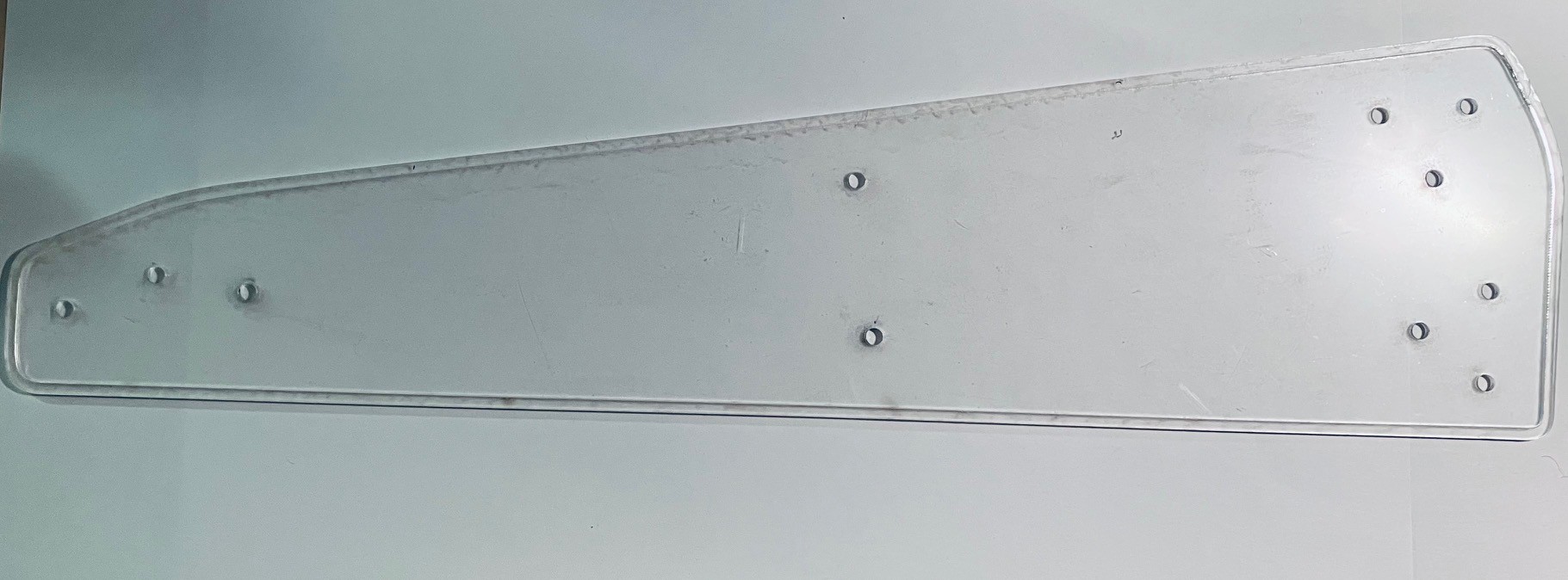
frame. The outside line represents the side panels as printed, while the inside outline is 3 mm smaller and is used to make an inner frame to support the top panels. Holes indicate positions where screws (#6 x 3/4 inch) will be used to attach the printed side panels to the inner frame (black dots), and attach flanges for 1/2 inch doweling to the inside frame (#6 x 1/2inch screws). I laser cut the template from a scrap of acrylic I had lying around to use as a positioning guide for the screw holes.
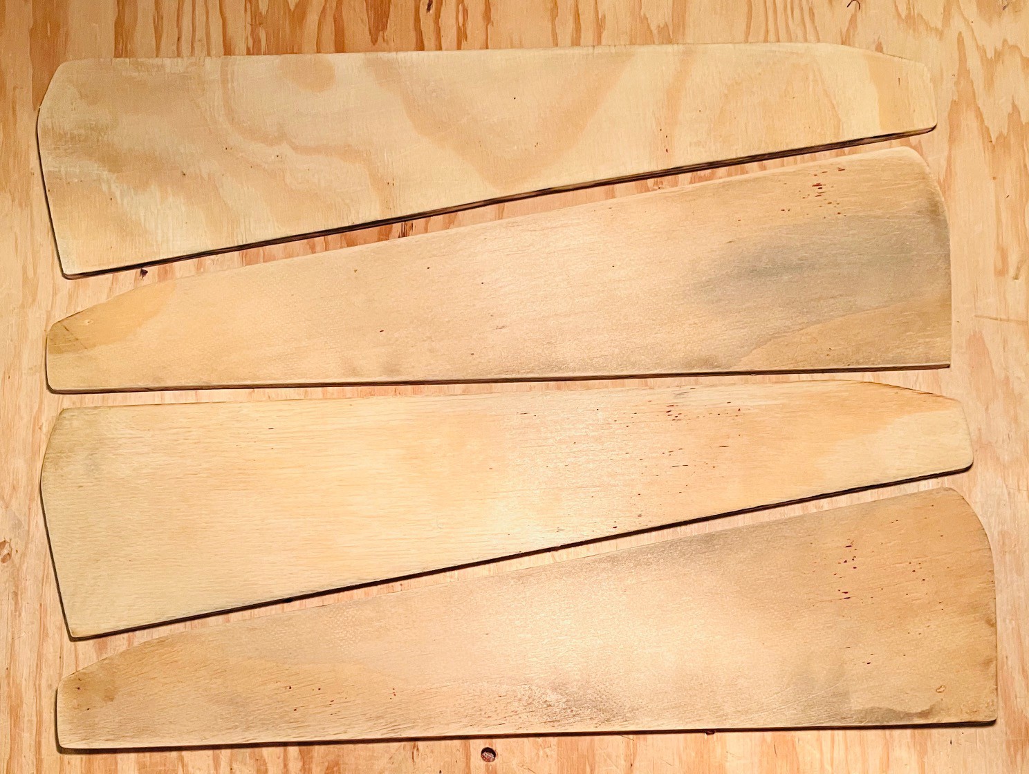
Then I laser cut four of the smaller pieces from 6 mm plywood.
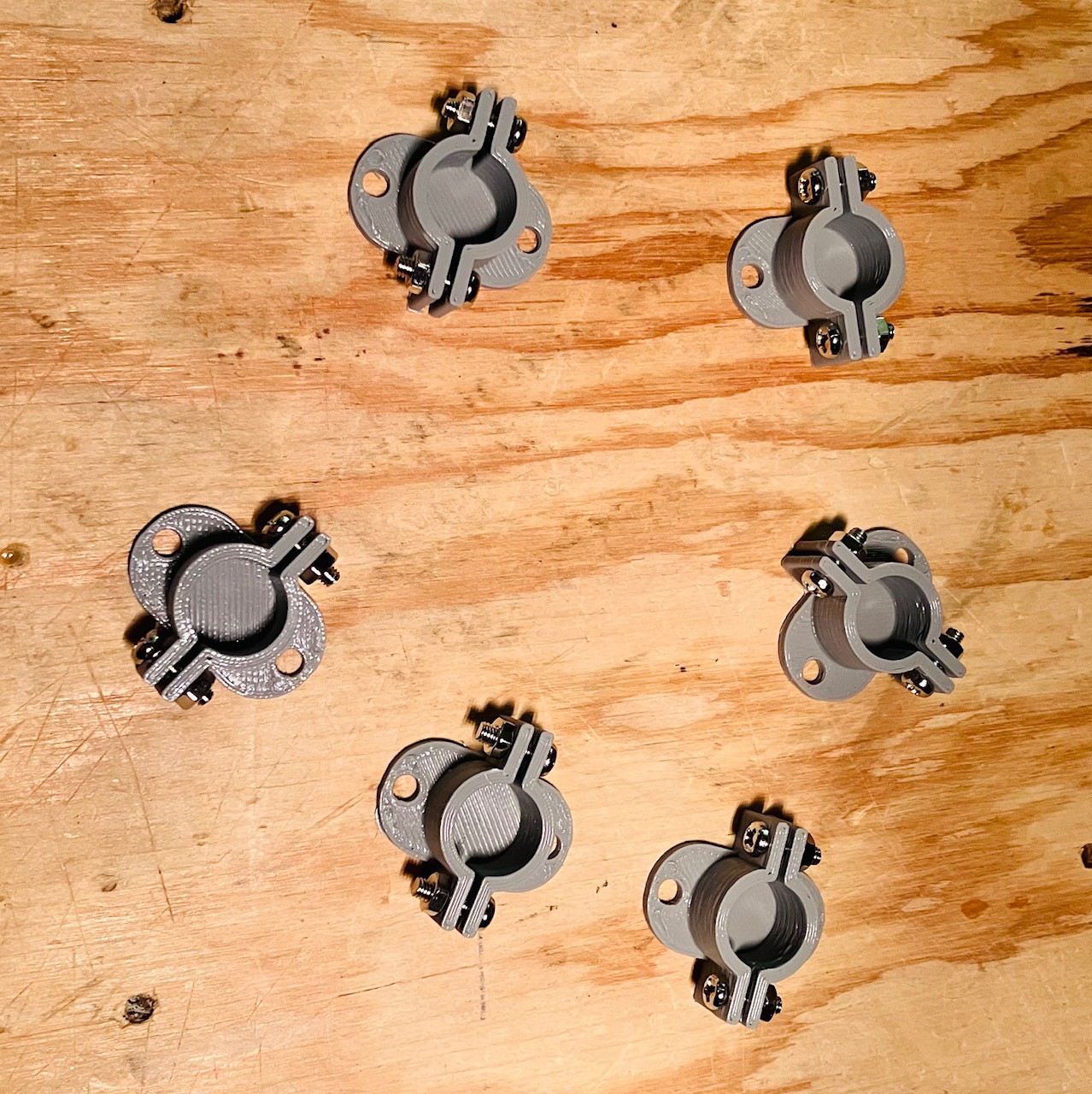
I designed and printed six flanges to anchor 1/2 inch dowels.
Then I glued two panels together for each inside frame and mounted the flanges based on the template.
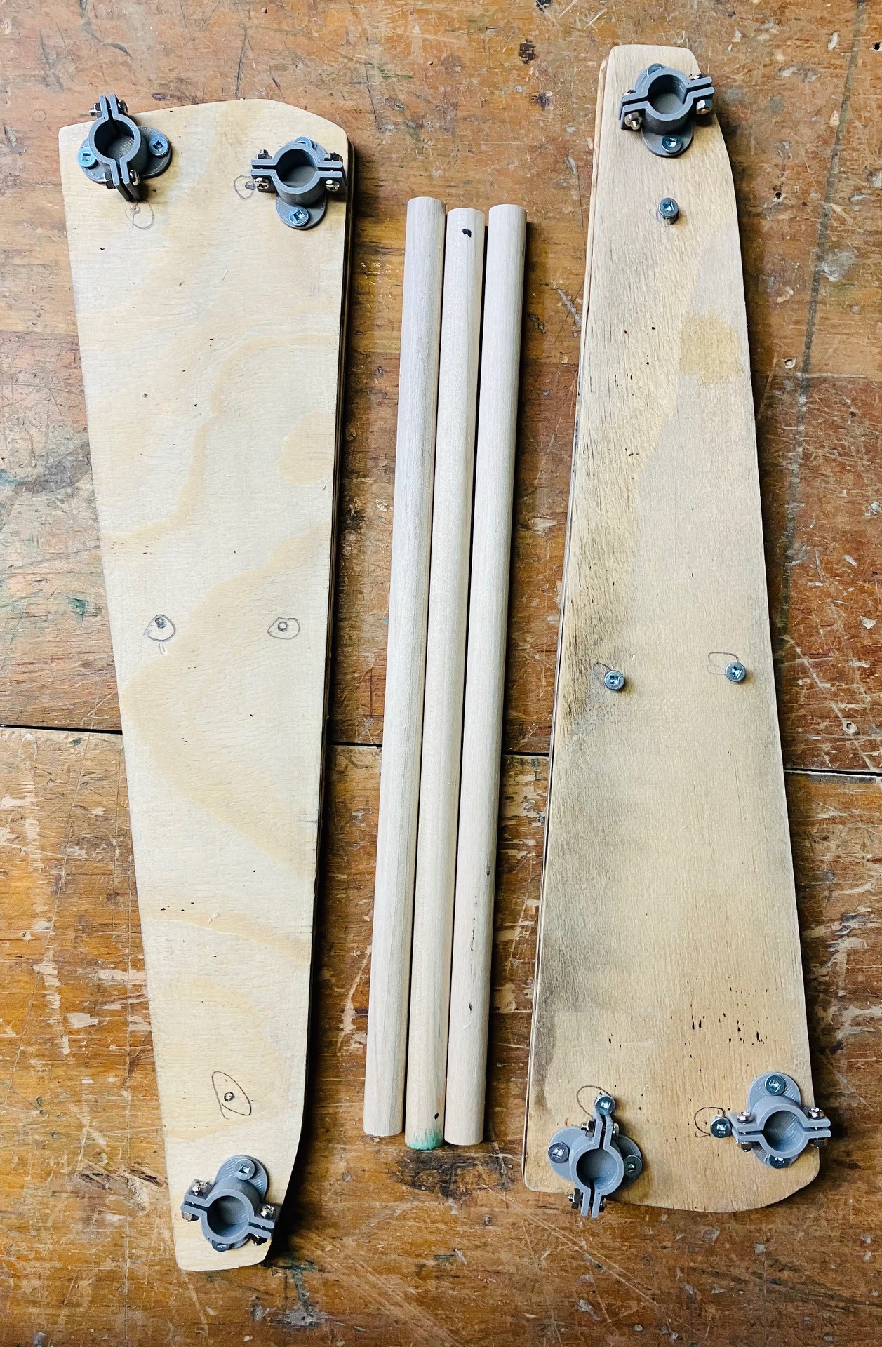
The dowels were cut so that the width of the machine from the outside edges of the inner frames is exactly 13.25 inches just as it is in the original. I attached the printed side panels to the inner frame pieces and inserted the dowels.
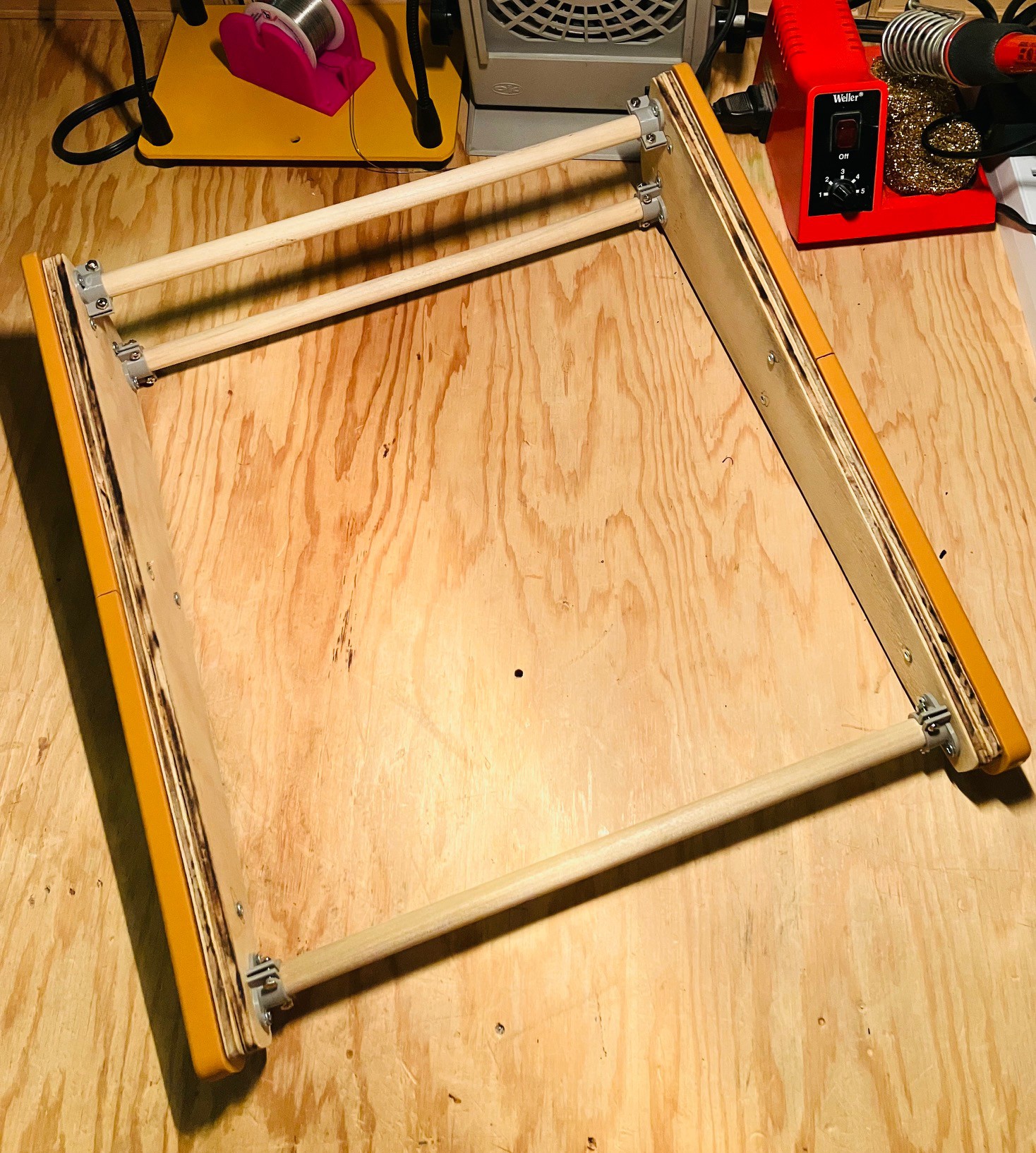
So I now have a solid frame to which I will mount the rest of the MCM/70 components.
Discussions
Become a Hackaday.io Member
Create an account to leave a comment. Already have an account? Log In.