With all the pieces done it was time to put it all together, but first I did one final check of the integrated electronics.
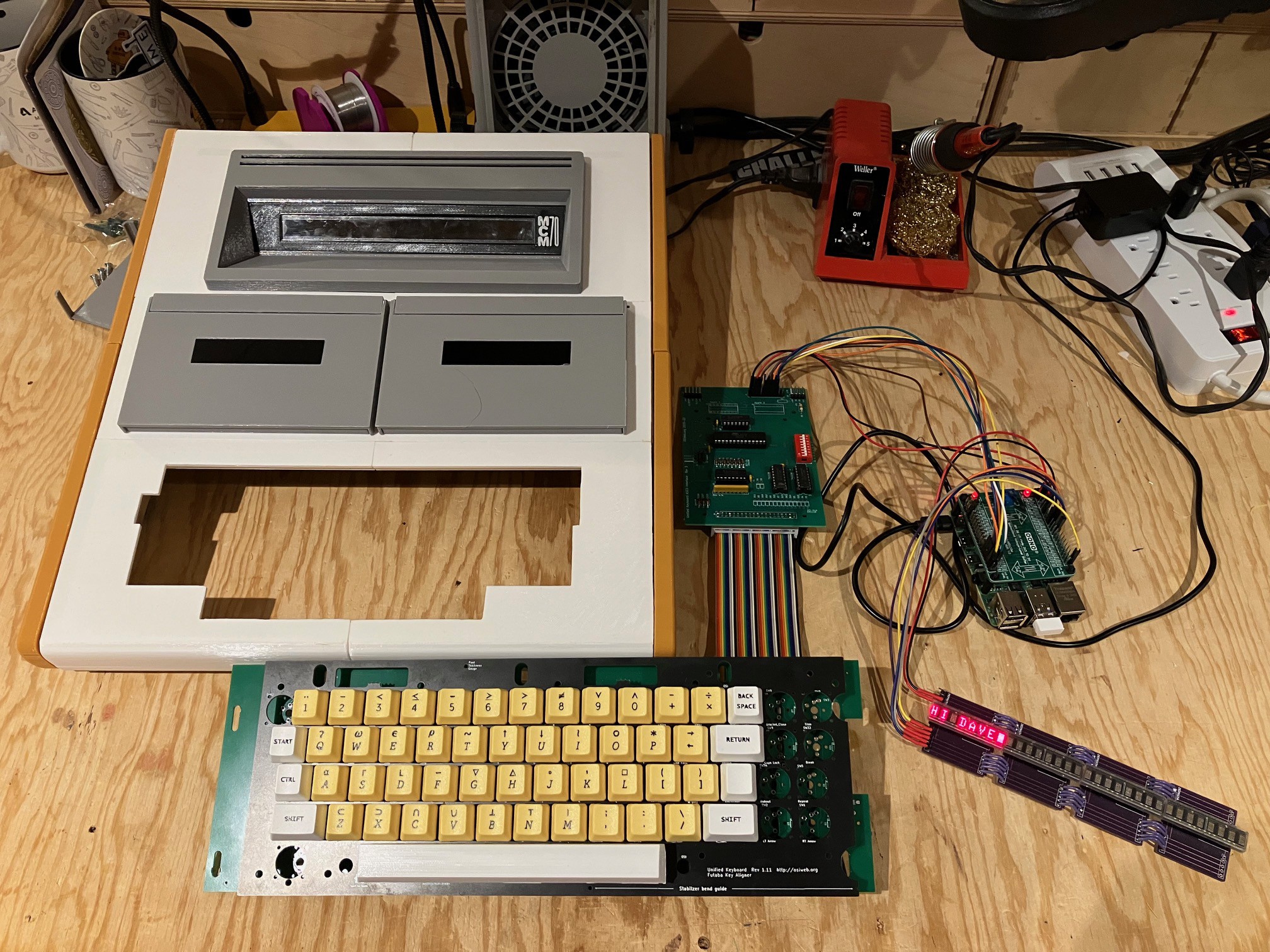
All good. Next:
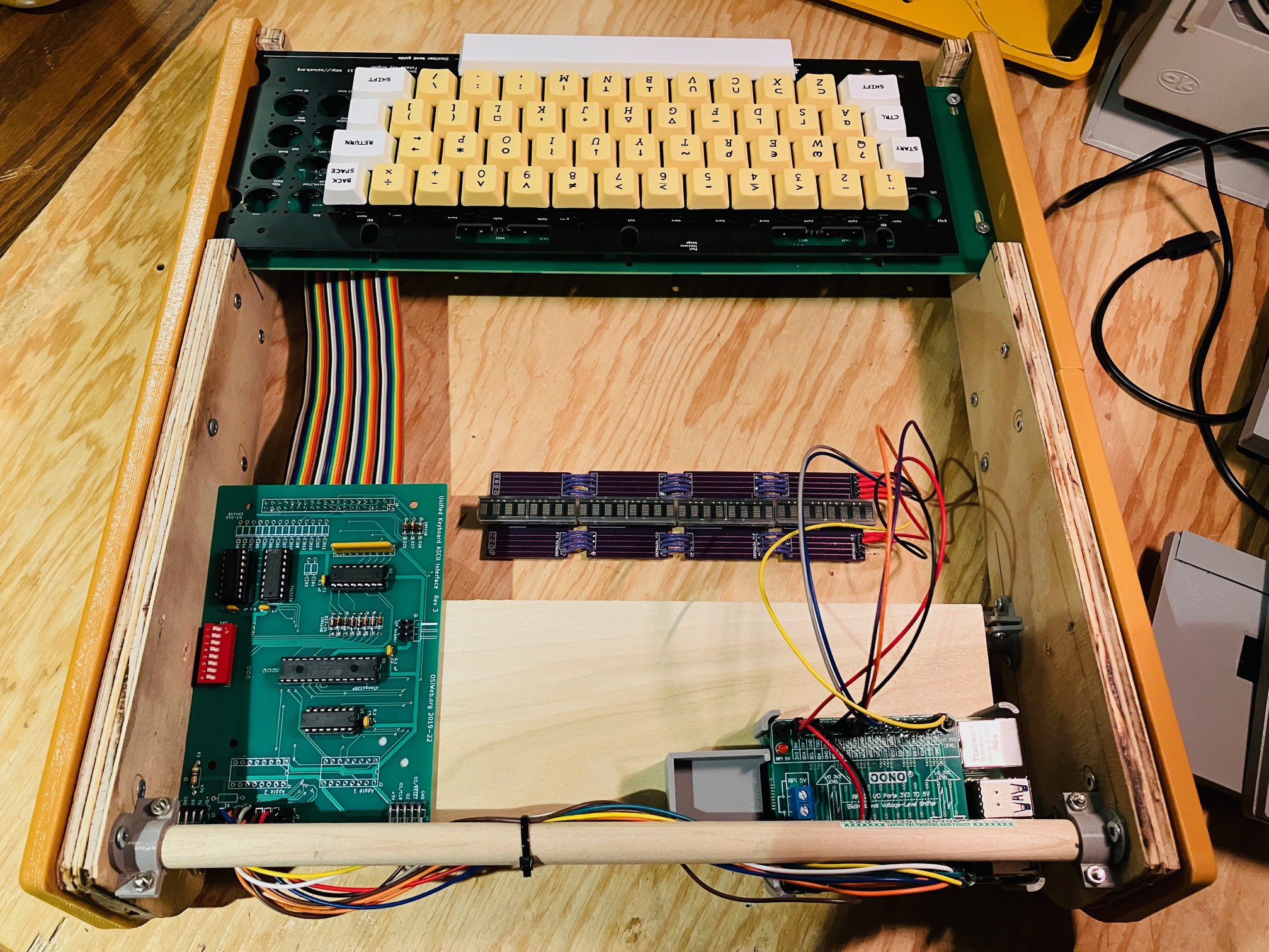
- I reinstalled the keyboard.
- Attached the keyboard encoder to the platform at the back of the case with some two sided tape.
- Positioned the 3D printed caddy for the Raspberry Pi on the platform as far back as it would go. (until the blue power connector hits the support dowel). Attach it in place with two sided tape and inserted the Raspberry pi.
Then:
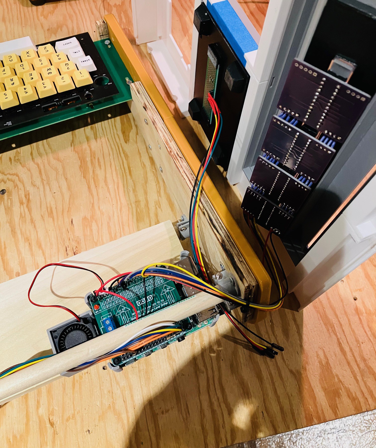
- Placing the top cover on it's side I carefully attached the display unit and left hand tape deck. I used a little blue tape along the opening edges for the cassette deck and display to ensure a tight fit.
- I ran the wires from the tape deck out through the back of the case.
- I also installed a little muffin fan (30x30x10 mm) on to the Raspberry Pi caddy and powered it from the 5V side of the Pi hat.
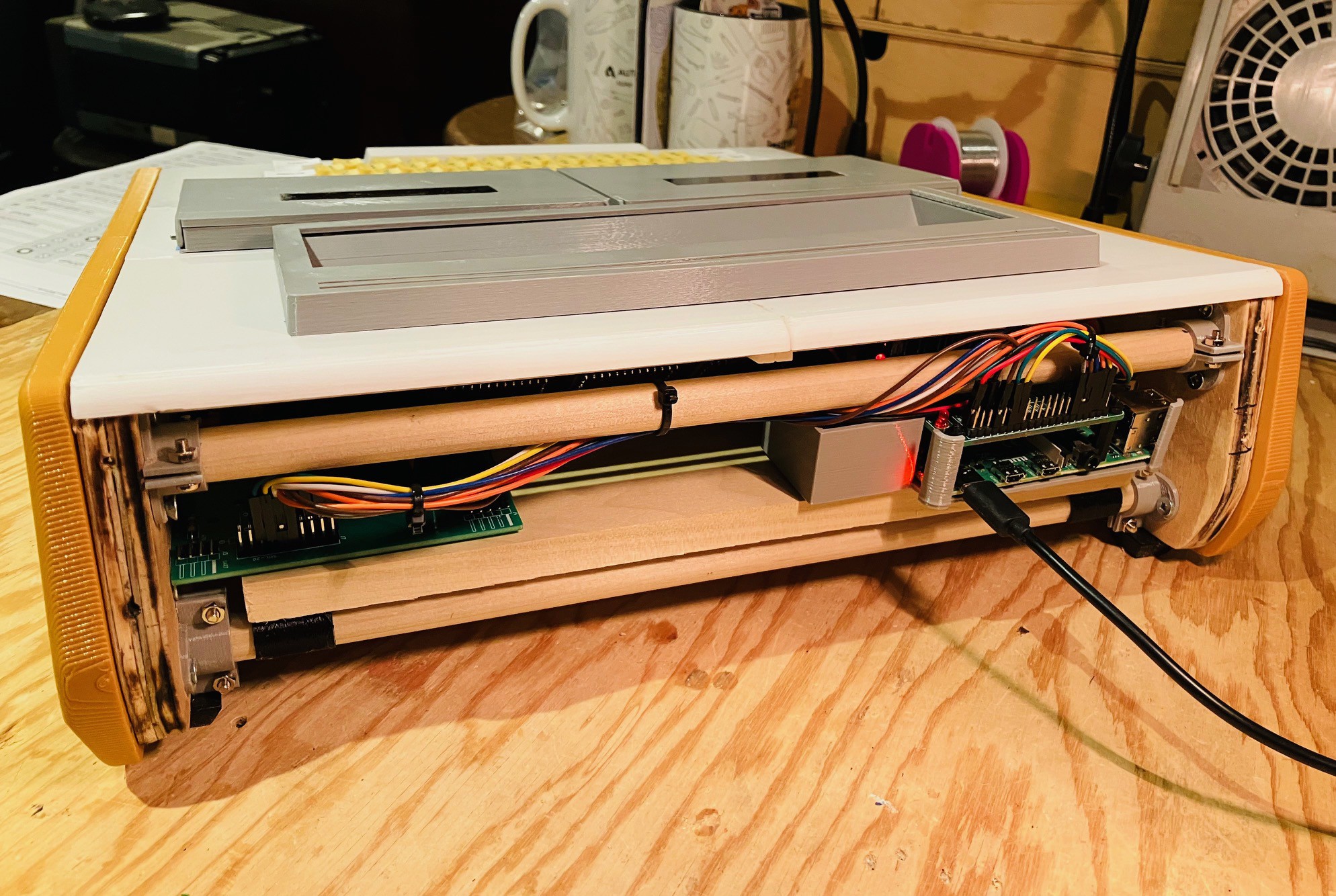
I positioned the Top Panel in place being careful not to the pull or pinch any of the wires.
The tape deck was wired to the following pins:
| Tape Sensor Module | Raspberry Pi | Description |
|---|---|---|
| 5V | 5V | Power |
| GND | GND | Ground |
| Hall Effect Sensor 1 | GPIO17 | Data Pin |
| Hall Effect Sensor 2 | GPIO27 | Data Pin |
I did a little cable management as well.
Finally, I reprinted the right hand side of the Back Panel with a cutout for the PI power, HDMI, and A/V Jack and attached it.
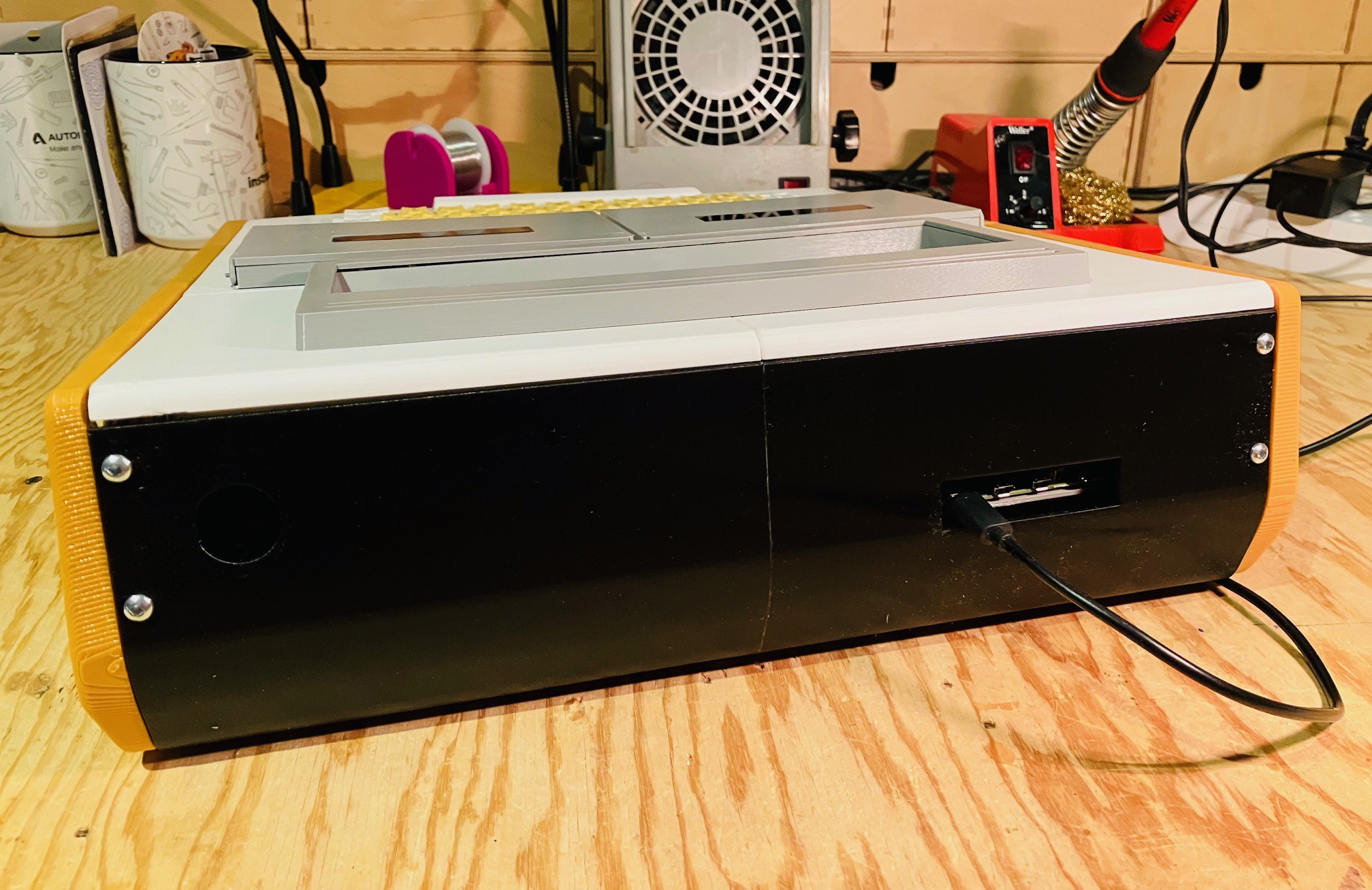
And that's it. The hardware is done!
I still have some software stuff to do like setting up the system to auto boot into the MCM/70 Emulator and integrating the tape deck sensors with the emulator, but this is a pretty big milestone for the project.
 Michael Gardi
Discussions
Become a Hackaday.io Member
Create an account to leave a comment. Already have an account? Log In.