 Guillermo Perez Guillen
Assembly of parts
Next, I show you some images of the assembly.
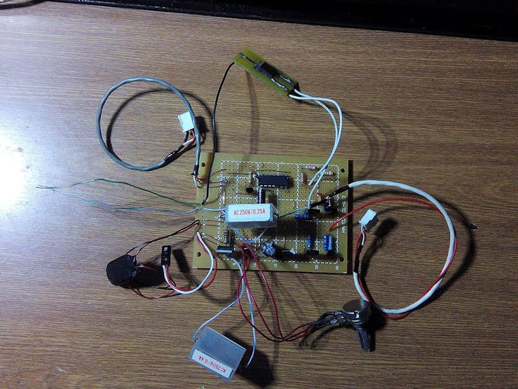
Soldering
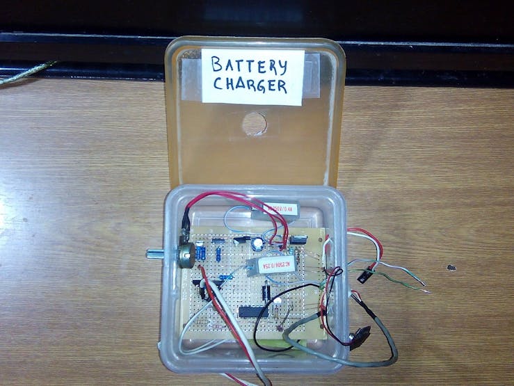
Protecting the board in a box
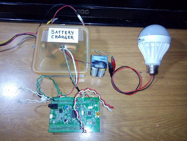
The prototype is finished
Test
Generating a PWM signal: This example requires a setpoint and the PWM signal is generated automatically.
Analysys
Generating a control PWM signal from a PIDController:
Setpoint: VBattery = 4.95 volts / VR5 = 2, 2 volts / ADC = 3003 ADC.
We can appreciate, here the PID controller, generates many duties cycles.
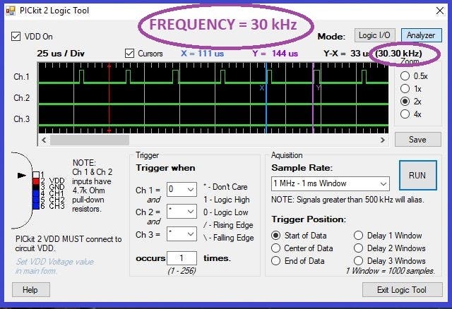
Measured frequency = 30 kHz
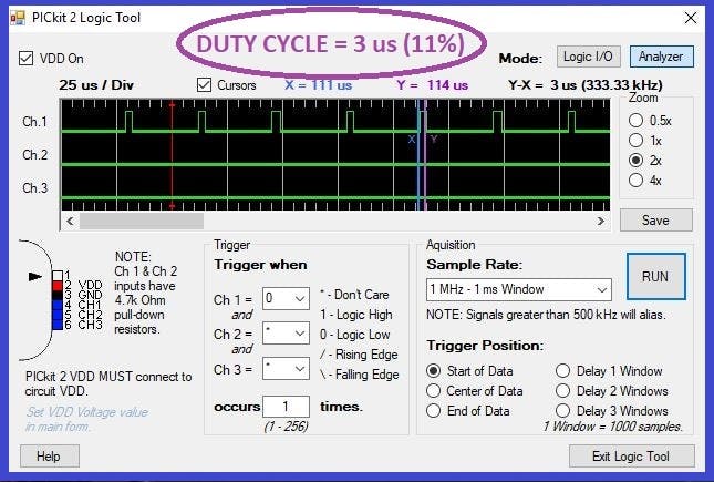
VR5 = 2,2 volts, duty cycle = 11%
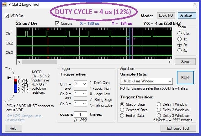
VR5 = 1,99 volts, duty cycle = 12%
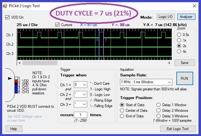
VR5 = 1,6 volts, duty cycle = 21%

VR5 = 1,3 volts, duty cycle = 24%
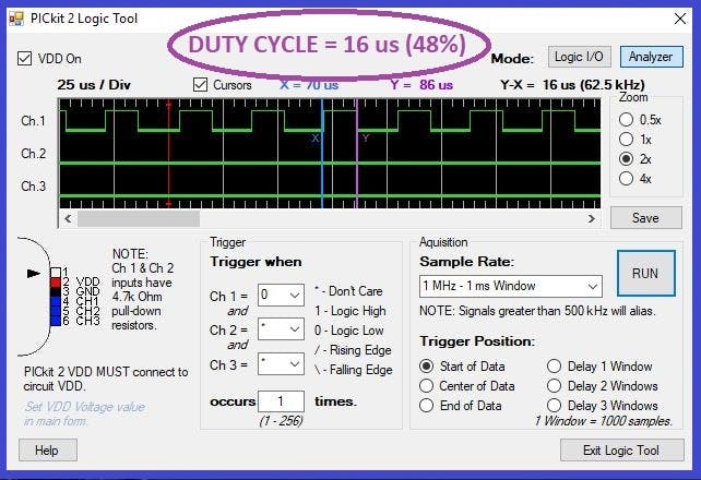
VR5 = 1,13 volts, duty cycle = 48%

VR5 = 0,9 volts, duty cycle = 91%
Discussions
Become a Hackaday.io Member
Create an account to leave a comment. Already have an account? Log In.