 Wenting Zhang
View video about this project on YouTube:
I highly suggest watching the video. The following is the transcript of the video:
Hello everyone, it has been a while. This video I would like to share one of the projects I finished recently, ELterm. Which stands for electroluminescence terminal. I bought these Planar 640 by 480 electroluminescence screens a few months back. The display is sort of similar to OLED, but it’s monochrome. These dot matrix screens typically emit yellow or amber ish color, but there are also models which are red and green dual color. Naturally I want to make something with this screen, and I decided to make a serial terminal with it, so let’s get started.
This video contains the following parts:
- Processor selection and overall design
- Making the hardware
- Writing the driver for EL screen
- Implement the serial terminal
- Final result
First is about the processor selection. I would like to implement the whole thing with just a microcontroller. The serial terminal part should be okay, the original VT220 was based on a microcontroller anyway. But refreshing the screen might not. Most of the dot matrix display technology requires constant refreshing, like at 60Hz. Screen modules that’s commonly used with microcontrollers are self-refresh screens. The screen module has its own memory and controller, and would refresh from its own memory without microcontroller intervention. For example, like these OLED modules, while the OLED needs constant refreshing, I could just disconnect the microcontroller, and it keeps the display. There exists self-refreshing EL screens, but the one I have isn’t. It demands to be refreshed at 120Hz, which means the microcontroller needs to continuously push data to the screen at 120Hz.
This put some requirements on the microcontroller. It would either hold the entire framebuffer in the RAM, or it could generate image data at screen refreshing speed. Both works, but bing able to store the frame buffer would be a bit more flexible. Then it should be able to generate the timing needed by the screen. Obviously one could do this with an FPGA, and I do have an FPGA video coming up in the future, but that’s for another time. For this time, many of the 32bit microcontroller works here, I chose the RP2040 from Raspberry Pi.
Here are the main spec for the RP2040. Dual-core Cortex-M0, 264KB SRAM, no internal Flash, executes code from SPI flash. The most important part for this project is it has PIO, which is a micro-code programmable IO module. I will show how to use it to drive the screen.
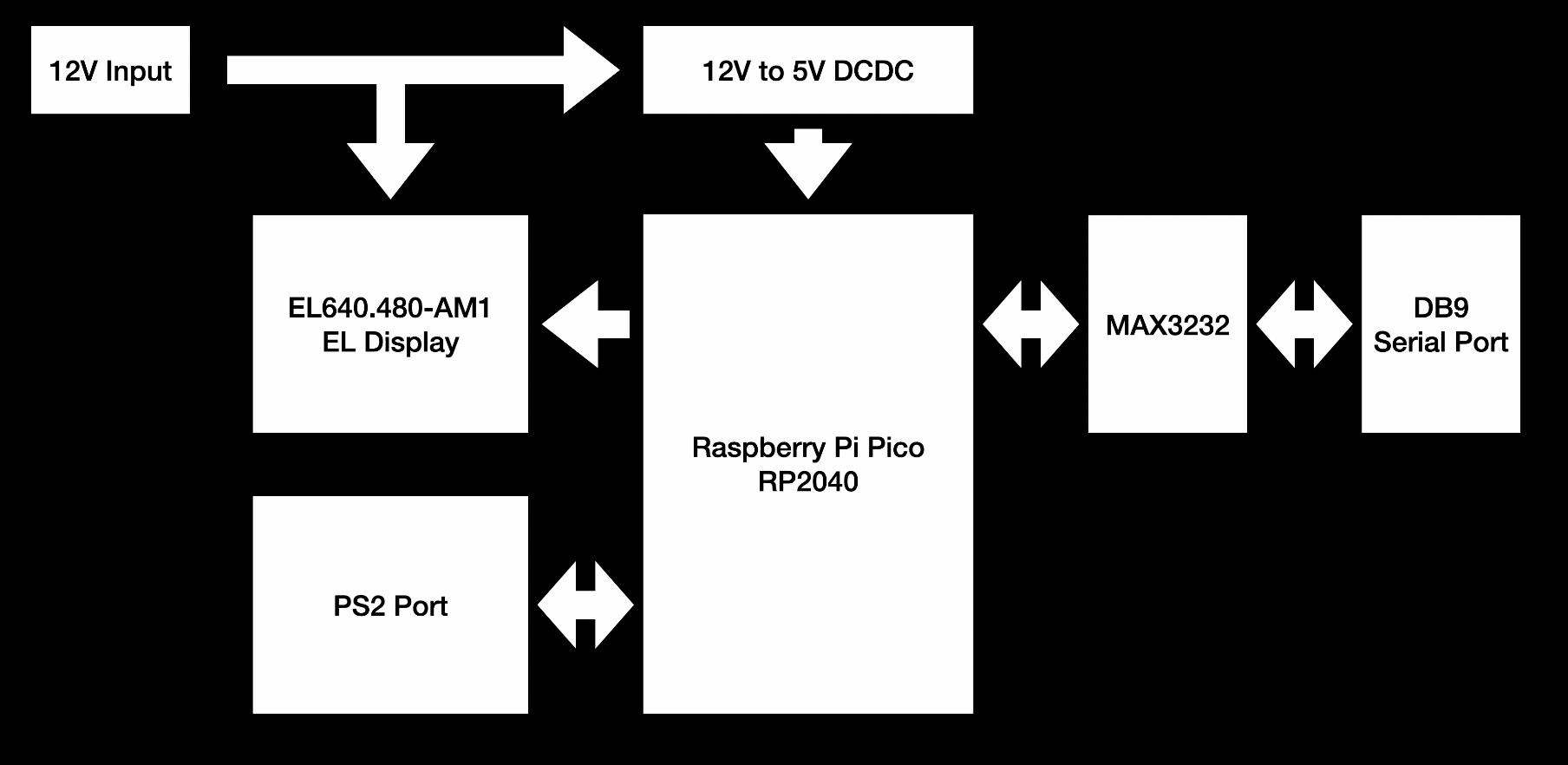
Now let’s take a look at the overall design. With the microcontroller in, I just need to fill in the interfaces I need. The screen doesn’t need any extra interface chips, and could be connected directly to the microcontroller. The terminal needs keyboard input, so adding a PS2 port here. Of course I could also just use the USB port of RP2040 itself. At last, the terminal needs a serial port, so adding a MAX3232 for a RS232 port, with jumpers for TTL serial options. For the power supply, the screen has internal high voltage generation, so only a 12V is needed. I decided to use 12V input for the whole board, and then use a 12V to 5V DCDC to power the Raspberry Pi Pico.
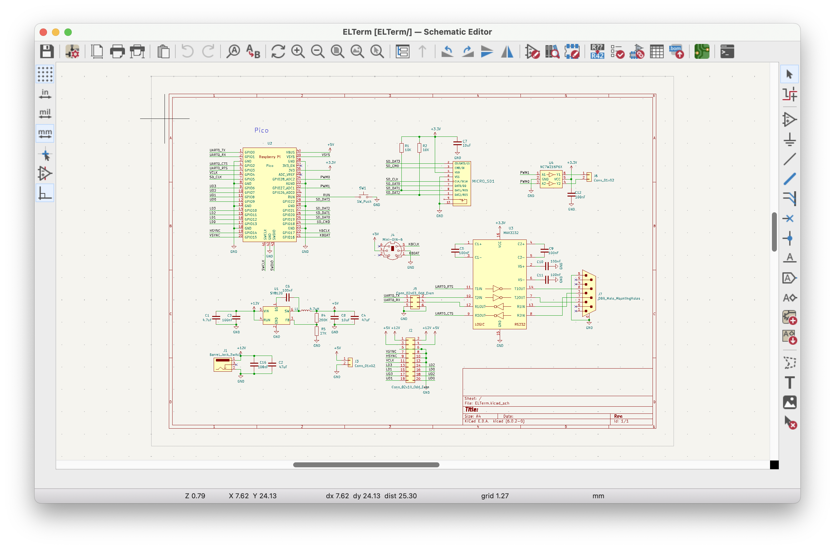
Then comes routing the board. To keep things simple, I am using the Pico as a module and mounting it directly on the board. There isn't much special about this board. So I am not going into details.
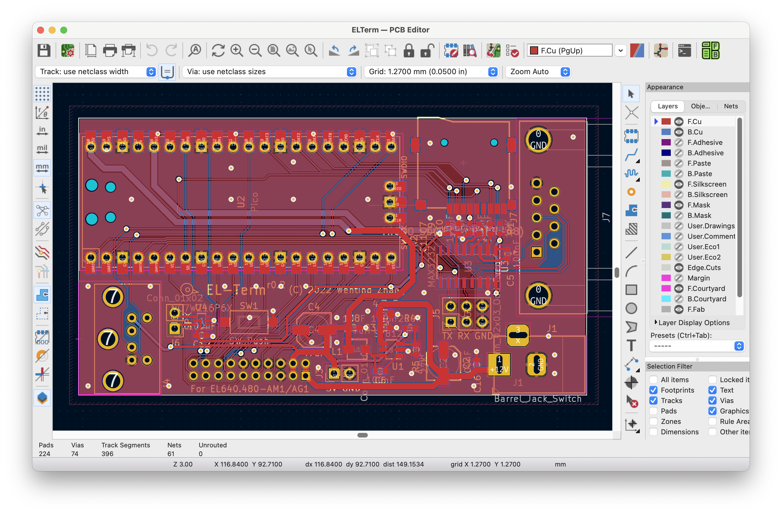
Once done, exporting the Gerber, submitting to the manufacturer, and a few days later I got the board. Then soldering the board. I usually solder the capacitors and resistors first, then chips, and last the connectors. There isn't much stuff on this board, and to be honest, I have been mostly working on more complex boards like with FPGA or SoC or DDR, and it’s refreshing to work with these simple 2-layer microcontroller boards again.
Now it’s time for coding. First about the screen driving. There are clear timing requirements in the screen datasheet. The screen is divided into upper half and lower half, and they are being refreshed simultaneously. Refreshing process is also quite straightforward, just send the pixels, send a horizontal sync when reaching the line end, and send a vertical sync on the first line. This sounds similar to a typical RGB or DPI signal, but the difference is that it transmits multiple pixels on each clock, and there are 2 raster beams instead of 1.
If I directly use GPIO to do that, it looks like this. First fetch the screen buffer address, then enter the loop. The loop only covers half of the screen as the screen has been divided vertically. Each line has 640 pixels divided by 8 pixels per byte equals 80 bytes. The data bus is 4 bit wide, so each byte takes 2 clocks. The code for sending each byte is simply setting the GPIO based on the bits, and sending a pulse on the clock line. Additionally, send the sync signals based on the previous description.
    uint8_t *rdptr_ud = framebuf;
    uint8_t *rdptr_ld = framebuf + SCR_STRIDE * SCR_HEIGHT / 2;
    for (int y = 0; y < 480 / 2; y++) {
        for (int x = 0; x < 640 / 8; x++) {
            uint8_t du = *rdptr_ud++;
            uint8_t dl = *rdptr_ld++;
            for (int b = 0; b < 2; b++) {
                gpio_put(PIXCLK_PIN, 1);
                gpio_put(LD0_PIN, dl & 0x01);
                gpio_put(LD1_PIN, dl & 0x02);
                gpio_put(LD2_PIN, dl & 0x04);
                gpio_put(LD3_PIN, dl & 0x08);
                gpio_put(UD0_PIN, du & 0x01);
                gpio_put(UD1_PIN, du & 0x02);
                gpio_put(UD2_PIN, du & 0x04);
                gpio_put(UD3_PIN, du & 0x08);
                gpio_put(PIXCLK_PIN, 0);
                dl >>= 4;
                du >>= 4;
            }
        }
        gpio_put(HSYNC_PIN, 1);
        gpio_put(VSYNC_PIN, (y == 0) ? 1 : 0);
        delay(15);
        gpio_put(HSYNC_PIN, 0);
        delay(5);
        gpio_put(VSYNC_PIN, 0);
    }
It should be obvious that such code is not efficient at all. And here is the result if I run it. It works, but it’s quite flickery. If measured with an oscilloscope, the current refresh rate is about 64Hz. It’s kinda far away from 120Hz, or in other words, it needs to use 188% of the processor to achieve 120Hz refresh rate.
Now on to improve that. The obvious thing to optimize is not using bit tests to output data, but directly shifting and writing to the GPIO output register. Or even better, we have the PIO, which could do the shifting and outputting at a preset clock rate. The PIO needs some microcode for operation. For the first test, the code is simple:
.program el_udata
.side_set 1
.wrap_target
    out pins, 4     side 1
    nop             side 0
.wrap
The out command is for outputting data signal, and side is for outputting the clock signal. The code outputs 4 bit data and set the clock high in the first cycle, and set clock low in the second cycle. Then it wraps around.
The screen needs 2 data streams, for the upper and lower part respectively. I am going to just use 2 PIO state machines.
Put the sync signals aside, directly modify the code to use PIO for data output:
static inline void elsm_put(uint32_t ud, uint32_t ld) {
    while (pio_sm_is_tx_fifo_full(el_pio, EL_UDATA_SM));
    *(volatile uint32_t *)&el_pio->txf[EL_UDATA_SM] = ud;
    *(volatile uint32_t *)&el_pio->txf[EL_LDATA_SM] = ld;
}

static inline void elsm_wait(void) {
    uint32_t sm_stall_mask = 1u << (EL_UDATA_SM + PIO_FDEBUG_TXSTALL_LSB);
    el_pio->fdebug = sm_stall_mask;
    while (!(el_pio->fdebug & sm_stall_mask));
}


static void frame(void) {
    uint32_t *rdptr_ud = (uint32_t *)framebuf;
    uint32_t *rdptr_ld = (uint32_t *)(framebuf + SCR_STRIDE * SCR_HEIGHT / 2);
    for (int y = 0; y < SCR_HEIGHT / 2; y++) {
        for (int x = 0; x < SCR_STRIDE / 4; x++) {
            uint32_t du = *rdptr_ud++;
            uint32_t dl = *rdptr_ld++;
            elsm_put(du, dl);
        }
        elsm_wait();
        gpio_put(HSYNC_PIN, 1);
        gpio_put(VSYNC_PIN, (y == 0) ? 1 : 0);
        delay(15);
        gpio_put(HSYNC_PIN, 0);
        delay(5);
        gpio_put(VSYNC_PIN, 0);
    }
}
The GPIO operations are now replaced with code filling FIFO of PIO. And it waits for the PIO to finish sending data before sending the synchronization signals.
PIO also needs some additional initialization. For example the clock frequency. At 120Hz refresh rate, that’s 120Hz by 240 lines by 160 transmissions, equals to 4.6 MHz output clock. The PIO always sends data at the configured clock rate, so the CPU just needs to be fast enough to feed the data, without needing additional delay code to match the frame rate.
The code is still not complete though. The current code doesn’t guarantee that two PIO state machines would always be in sync. For example here, it writes to the upper screen state machine, then writes to the lower screen. So the upper state machine would start working first. If lucky, both state machines would be in sync. If unlucky, the upper one would be leading the lower one, causing the image to be shifted. A simple way to solve that is to turn off the state machines, pre fill some data into the FIFO, and start the 2 state machines in sync.
static void frame(void) {
    uint32_t *rdptr_ud = (uint32_t *)framebuf;
    uint32_t *rdptr_ld = (uint32_t *)(framebuf + SCR_STRIDE * SCR_HEIGHT / 2);
    for (int y = 0; y < SCR_HEIGHT / 2; y++) {
        pio_sm_set_enabled(el_pio, EL_UDATA_SM, false);
        pio_sm_set_enabled(el_pio, EL_LDATA_SM, false);
        // prefill FIFO
        elsm_put(*rdptr_ud++, *rdptr_ld++);
        // start SM
        pio_enable_sm_mask_in_sync(el_pio, (1u << EL_UDATA_SM) | (1u << EL_LDATA_SM));
        // loop filling FIFO
        for (int x = 1; x < SCR_STRIDE / 4; x++) {
            uint32_t du = *rdptr_ud++;
            uint32_t dl = *rdptr_ld++;
            elsm_put(du, dl);
        }
        elsm_wait();
        gpio_put(HSYNC_PIN, 1);
        gpio_put(VSYNC_PIN, (y == 0) ? 1 : 0);
        delay(15);
        gpio_put(HSYNC_PIN, 0);
        delay(5);
        gpio_put(VSYNC_PIN, 0);
    }
}
Now run the code, the flickery is mostly gone, and now we have a steady 120Hz.
Though it displays just fine, the CPU spends all of its time on displaying the image, with no resource for other stuff, like implementing the actual serial terminal. There are 2 solutions, one is to just not solve it at all, use another CPU core to do other stuff. Another is to use DMA and interrupt, using the DMA to send data to the PIO. DMA is basically a hardware memory copier, and the CPU just needs to tell the DMA where to copy the data. I am going to use the DMA method.
For the code, configuring the DMA to do a memory to peripheral copy. All the subsequent code could simply use DMA for copying data. Run the code again, and it should still work. It’s not done yet as it still eats all the CPU time. This step is just to make sure DMA works. Next step is to split stuff into interrupts.
static void el_dma_init() {
    el_udma_chan = dma_claim_unused_channel(true);
    dma_channel_config cu =
            dma_channel_get_default_config(el_udma_chan);
    channel_config_set_transfer_data_size(&cu, DMA_SIZE_32);
    channel_config_set_read_increment(&cu, true);
    channel_config_set_write_increment(&cu, false);
    channel_config_set_dreq(&cu, DREQ_PIO0_TX0 + EL_UDATA_SM);

    dma_channel_configure(el_udma_chan, &cu,
            &el_pio->txf[EL_UDATA_SM],
            NULL, SCR_STRIDE / 4, false);

    el_ldma_chan = dma_claim_unused_channel(true);
    dma_channel_config cl =
            dma_channel_get_default_config(el_ldma_chan);
    channel_config_set_transfer_data_size(&cl, DMA_SIZE_32);
    channel_config_set_read_increment(&cl, true);
    channel_config_set_write_increment(&cl, false);
    channel_config_set_dreq(&cl, DREQ_PIO0_TX0 + EL_LDATA_SM);

    dma_channel_configure(el_ldma_chan, &cl,
            &el_pio->txf[EL_LDATA_SM],
            NULL, SCR_STRIDE / 4, false);
}

static void frame(void) {
    uint32_t *rdptr_ud = (uint32_t *)framebuf;
    uint32_t *rdptr_ld = (uint32_t *)(framebuf +
            SCR_STRIDE * SCR_HEIGHT / 2);
    dma_channel_set_read_addr(el_udma_chan, rdptr_ud, false);
    dma_channel_set_read_addr(el_ldma_chan, rdptr_ld, false);

    for (int y = 0; y < SCR_HEIGHT / 2; y++) {
        pio_sm_set_enabled(el_pio, EL_UDATA_SM, false);
        pio_sm_set_enabled(el_pio, EL_LDATA_SM, false);
        // Setup DMA
        dma_channel_start(el_udma_chan);
        dma_channel_start(el_ldma_chan);
        // start SM
        pio_enable_sm_mask_in_sync(el_pio, (1u << EL_UDATA_SM) |
                (1u << EL_LDATA_SM));
        // Increment addr
        // Wait for finish
        dma_channel_wait_for_finish_blocking(el_udma_chan);
        dma_channel_wait_for_finish_blocking(el_ldma_chan);
        // Wait for SM to finish
        elsm_wait();
        gpio_put(HSYNC_PIN, 1);
        gpio_put(VSYNC_PIN, (y == 0) ? 1 : 0);
        delay(15);
        gpio_put(HSYNC_PIN, 0);
        delay(5);
        gpio_put(VSYNC_PIN, 0);
    }
}
Divide the refresh function into 3 parts, function for starting a new line, function for starting a new frame, and function for DMA handler. The DMA only transfers one line at a time, once that’s done, the DMA interrupt is called again. The synchronization signals are generated in the DMA interrupt, the code then decides to start the next line or start a new frame based on the current position.
static int el_cur_y = 0;

static void el_dma_start_frame() {
    uint32_t *rdptr_ud = (uint32_t *)framebuf;
    uint32_t *rdptr_ld = (uint32_t *)(framebuf +
            SCR_STRIDE * SCR_HEIGHT / 2);
    dma_channel_set_read_addr(el_udma_chan, rdptr_ud, false);
    dma_channel_set_read_addr(el_ldma_chan, rdptr_ld, false);
    el_dma_start_line();
}

static void el_dma_start_line() {
    pio_sm_set_enabled(el_pio, EL_UDATA_SM, false);
    pio_sm_set_enabled(el_pio, EL_LDATA_SM, false);
    // Setup DMA
    dma_channel_start(el_udma_chan);
    dma_channel_start(el_ldma_chan);
    // start SM
    pio_enable_sm_mask_in_sync(el_pio, (1u << EL_UDATA_SM) |
        (1u << EL_LDATA_SM));
}

static void el_dma_handler() {
    dma_hw->ints0 = 1u << el_udma_chan;

    elsm_wait();
    gpio_put(HSYNC_PIN, 1);
    gpio_put(VSYNC_PIN, (el_cur_y == 0) ? 1 : 0);
    delay(15);
    gpio_put(HSYNC_PIN, 0);
    delay(5);
    gpio_put(VSYNC_PIN, 0);
    el_cur_y ++;
    if (el_cur_y == SCR_HEIGHT / 2) {
        // End of frame, reset
        el_cur_y = 0;
        el_dma_start_frame();
    }
    else {
        el_dma_start_line();
    }
}
Finally, add code to enable the interrupt, and remove the call to the old refresh code, done. Now I can add other stuff into the main function without affecting the screen refresh. To measure the CPU load, I can add some GPIO toggling in the interrupt service routine. For example, if the IO is high, it’s in the interrupt, otherwise low. Measuring the signal, the duty cycle is about 46%, which means the CPU load is 46%. Note this measurement doesn’t include the interrupt overhead, of the actual load would be a tiny bit higher.
While 48% is much better than the initial 270%, but this is not ideal:
- There is a busy loop in the interrupt to generate the sync signal
- There is a busy loop in the interrupt to wait for the PIO to finish. DMA only pushes the data into PIO, but not waiting for the PIO to finish
- EL screen is sensitive to timing, if the CPU could not service the interrupt in time, it could cause display artifacts
The solution is to let PIO generate a sync signal alongside with putting out data.
Since we have 2 state machines here, I would assign one for Hsync, another for Vsync.
The overall code looks like this.
; UDATA SM handles UD0-3, PCLK, and VSYNC
; PCLK is mapped to SIDE, VSYNC is mapped to SET,
; and UD0-3 are mapped to OUT
.program el_udata
.side_set 1
    irq set 5 side 0
    mov x, isr side 0
loop_first_line:
    out pins, 4 side 1
    jmp x-- loop_first_line side 0
end_first_line:
    set pins, 1 [6] side 0
    set pins, 0 [9] side 0
line_start:
    irq set 5 side 0
    mov x, isr side 0
loop:
    out pins, 4 side 1
    jmp x-- loop side 0
loop_end:
    nop [15] side 0
    jmp y-- line_start side 0
    ; end of frame, signal CPU
    irq wait 1 side 0

; LDATA SM handles LD0-3 and HSYNC
; HSYNC is mapped to SET, and LD0-3 are mapped to OUT
.program el_ldata
    ; Signal UDATA SM to start outputting data
    mov x, isr
    wait irq 5
loop:
    out pins, 4
    jmp x-- loop
    ; toggle Hsync and signal Vsync SM
    set pins, 1 [5]
    set pins, 0 [10]
PIO needs to maintain 2 counters, for the X and Y position, conveniently, using the X and Y register. The X counter needs to be restarted each line, so I am saving the initial value into the ISR register, and the PIO would reload the value from that.
For the first line, both state machines need to output one line of data, and generate both horizontal and vertical sync. In the subsequent lines, only data and horizontal sync are needed. Looking at the code, both sides load the initial counter value, then the second state machine would wait for the first one to send an interrupt bit, then both start outputting data. After the first line, they would output the sync signals. The second state machine goes back to the loop, but the first one continues and goes on to the second loop. Once it has finished preset number of iterations, it would send an interrupt to the processor, and stop.
Finally, adding the configuration code, enabling PIO interrupt. In the interrupt, it needs to configure the DMA, setting the initial value for PIO, and restart the PIO.
static void el_pio_irq_handler() {
    gpio_put(25, 1);
    if (swap_buffer) {
        frame_state = !frame_state;
        swap_buffer = false;
    }uint8_t *framebuf = frame_state ? framebuf_bp1 : framebuf_bp0;

    uint32_t *rdptr_ud = (uint32_t *)(framebuf);
    uint32_t *rdptr_ld = (uint32_t *)(framebuf + SCR_STRIDE * SCR_HEIGHT / 2);
    dma_channel_set_read_addr(el_udma_chan, rdptr_ud, false);
    dma_channel_set_read_addr(el_ldma_chan, rdptr_ld, false);

    pio_sm_set_enabled(el_pio, EL_UDATA_SM, false);
    pio_sm_set_enabled(el_pio, EL_LDATA_SM, false);

    pio_sm_clear_fifos(el_pio, EL_UDATA_SM);
    pio_sm_clear_fifos(el_pio, EL_LDATA_SM);

    pio_sm_restart(el_pio, EL_UDATA_SM);
    pio_sm_restart(el_pio, EL_LDATA_SM);

    // Load configuration values
    el_sm_load_reg(EL_UDATA_SM, pio_y, SCR_REFRESH_LINES - 2);
    el_sm_load_reg(EL_UDATA_SM, pio_isr, SCR_LINE_TRANSFERS - 1);
    el_sm_load_reg(EL_LDATA_SM, pio_isr, SCR_LINE_TRANSFERS - 1);

    // Setup DMA
    dma_channel_start(el_udma_chan);
    dma_channel_start(el_ldma_chan);
    // Clear IRQ flag
    el_pio->irq = 0x02;
    // start SM
    pio_enable_sm_mask_in_sync(el_pio, (1u << EL_UDATA_SM) | (1u << EL_LDATA_SM));
    gpio_put(25, 0);
}
Running it now, we could see the interrupt is only taking 1.5 microseconds of time, and it’s being fired 120 times per second. This translates to a CPU load of only 0.02%. This is a huge improvement.
While it’s possible to remove this interrupt entirely, letting the PIO to reload the Y register value itself, and letting the DMA working in a chained loop, I am not going to do that for the following reasons. Precise vertical interrupts are extremely helpful for implementing double buffering, or implementing greyscale.
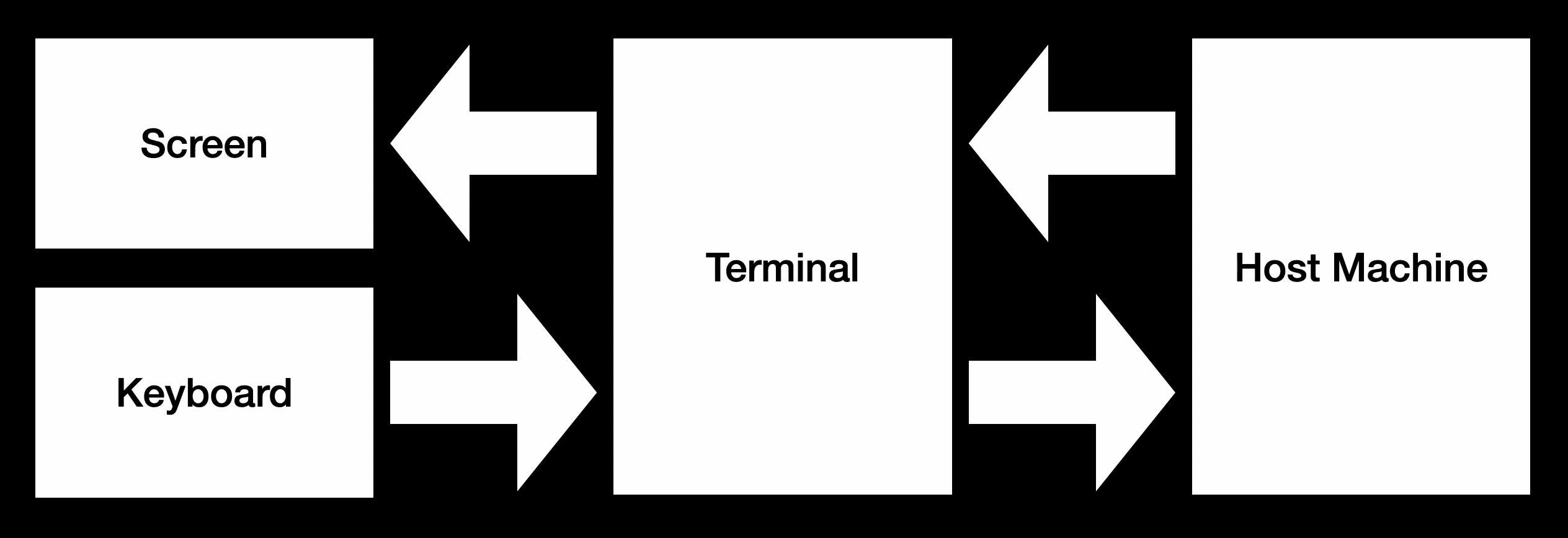
With the display sorted out, the next step is implementing the serial terminal. It might sound easy, which is basically displaying whatever received from the serial port, and sending out whatever user typed to the serial port. So let’s do it. Prepare a suitable dot matrix font, write code for displaying the text, building a software FIFO for buffering data received in the serial interrupt and fetched in the main loop. Keyboard wise, RP2040 SDK has built in support for USB keyboards using the TinyUSB library, so it’s just a matter of translating the keycode into ascii and sending them. Easy enough right.
Unfortunately no. Obvious issues, there is no arrow key, function key, or paging keys in the ASCII. How do I send these? Then, typically the host needs to send more than just texts to the terminal. It also needs to tell the terminal where to put the text, what color the text should have, etc. All these are implemented with escape sequences. For example, to move the cursor to position 2,4, one could use a sequence like this to implement. Host just needs to send this sequence, and the terminal should parse and do the corresponding task.
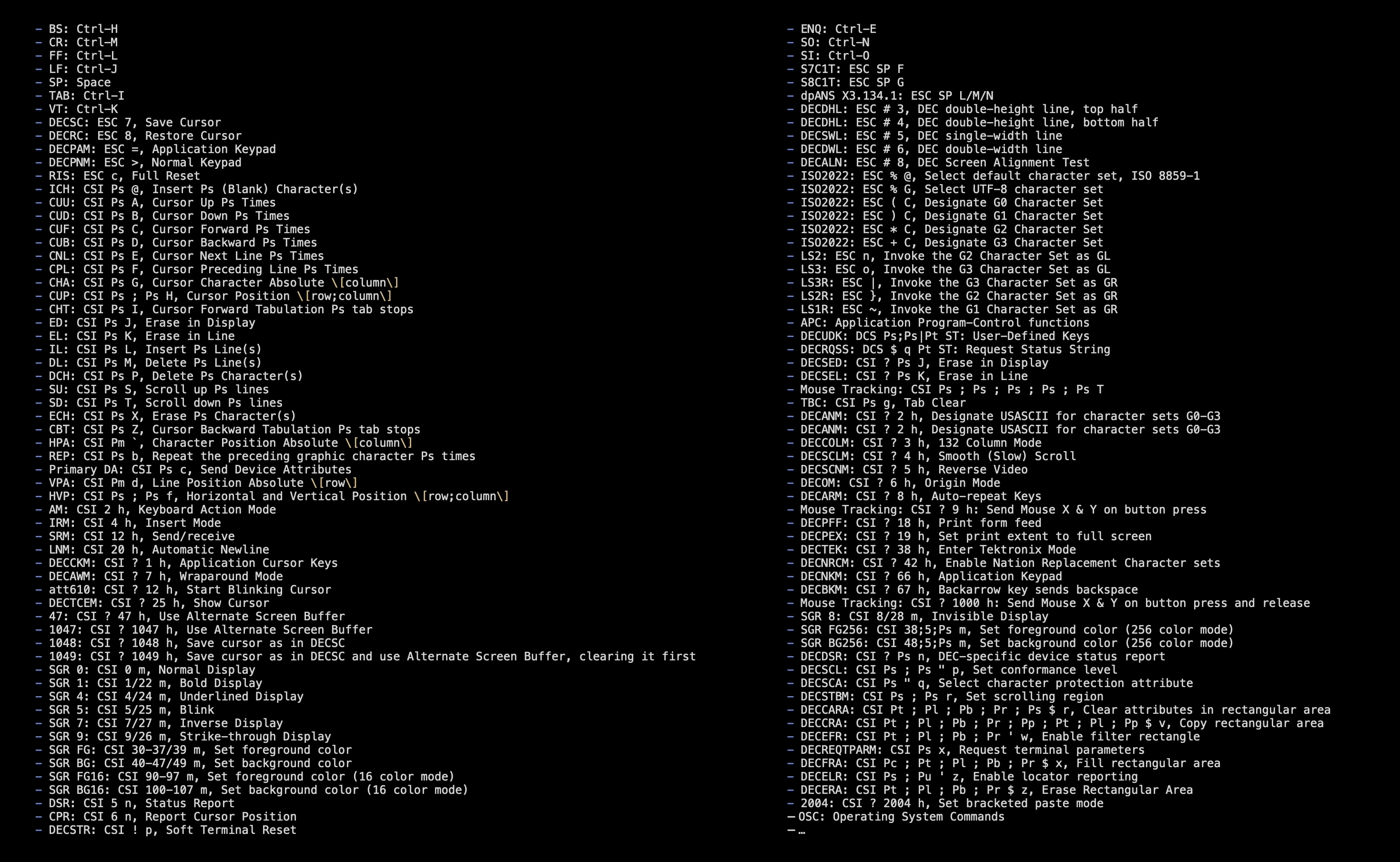
There are lot of such sequences. I selected and implemented a few supported by xterm. Which also implies there are tons more I didn’t support. Plus there are even more subtle behavior differences between terminal standards, which could be quite daunting to figure out and implement correctly.
For example, imagine the host keeps spitting out texts, until one line has been filled up. If it keeps printing, then the text would go to the next line by default. But where should the cursor be by the time it has just been filled up? What if the application requests to move the cursor at this time? Does that happen before moving to the next line, or after?
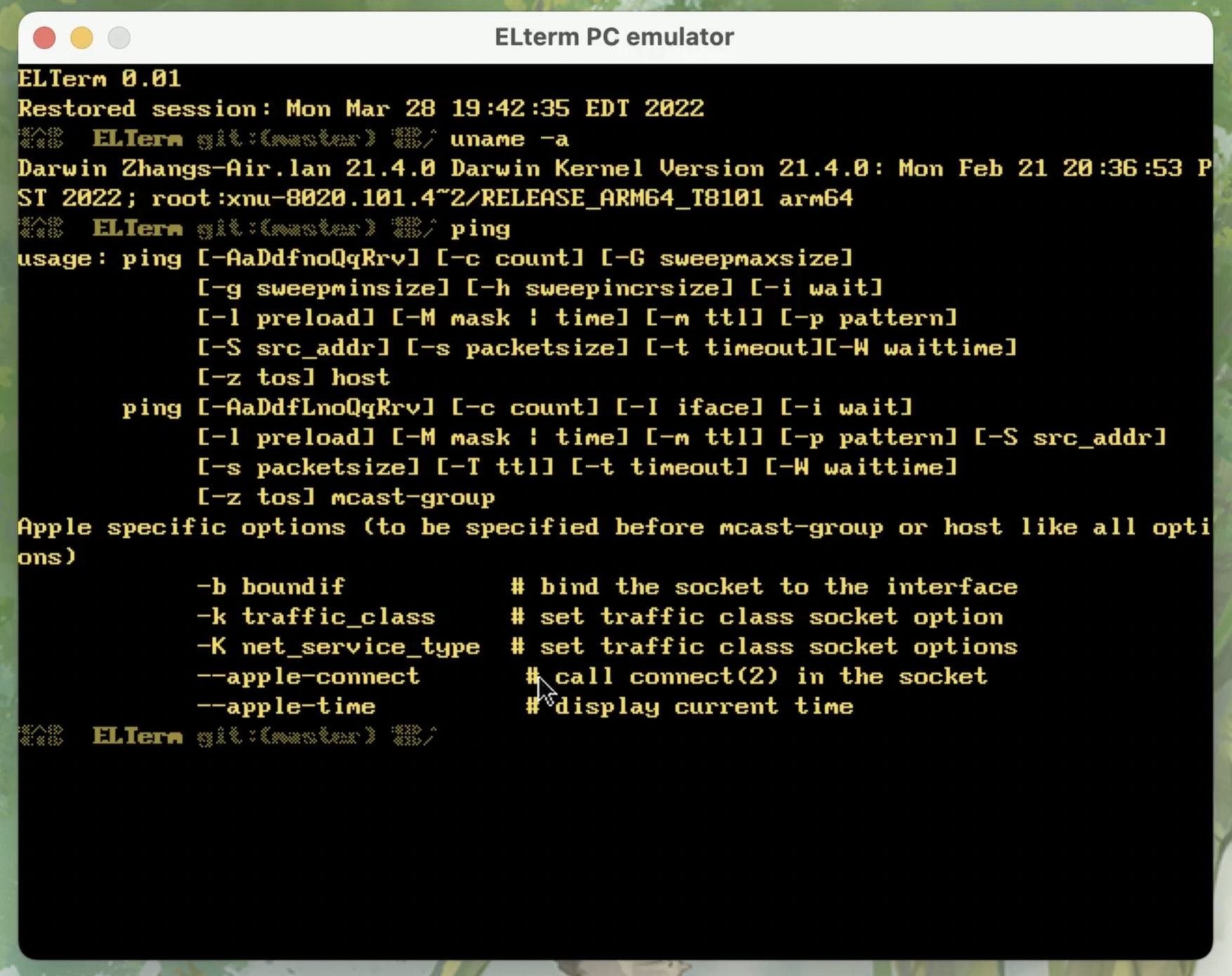
To help with debugging and testing, I ended up porting the entire firmware onto Linux and macOS, so it functions as a terminal emulator. In conclusion, if one is looking to build a usable terminal, I will still suggest looking into existing libraries, such as libtmt or libtsm. But otherwise, it could be fun to start from scratch.
Now let’s run it and see it in action. I am connecting it directly to the Raspberry Pi:
Like running ping, or running htop
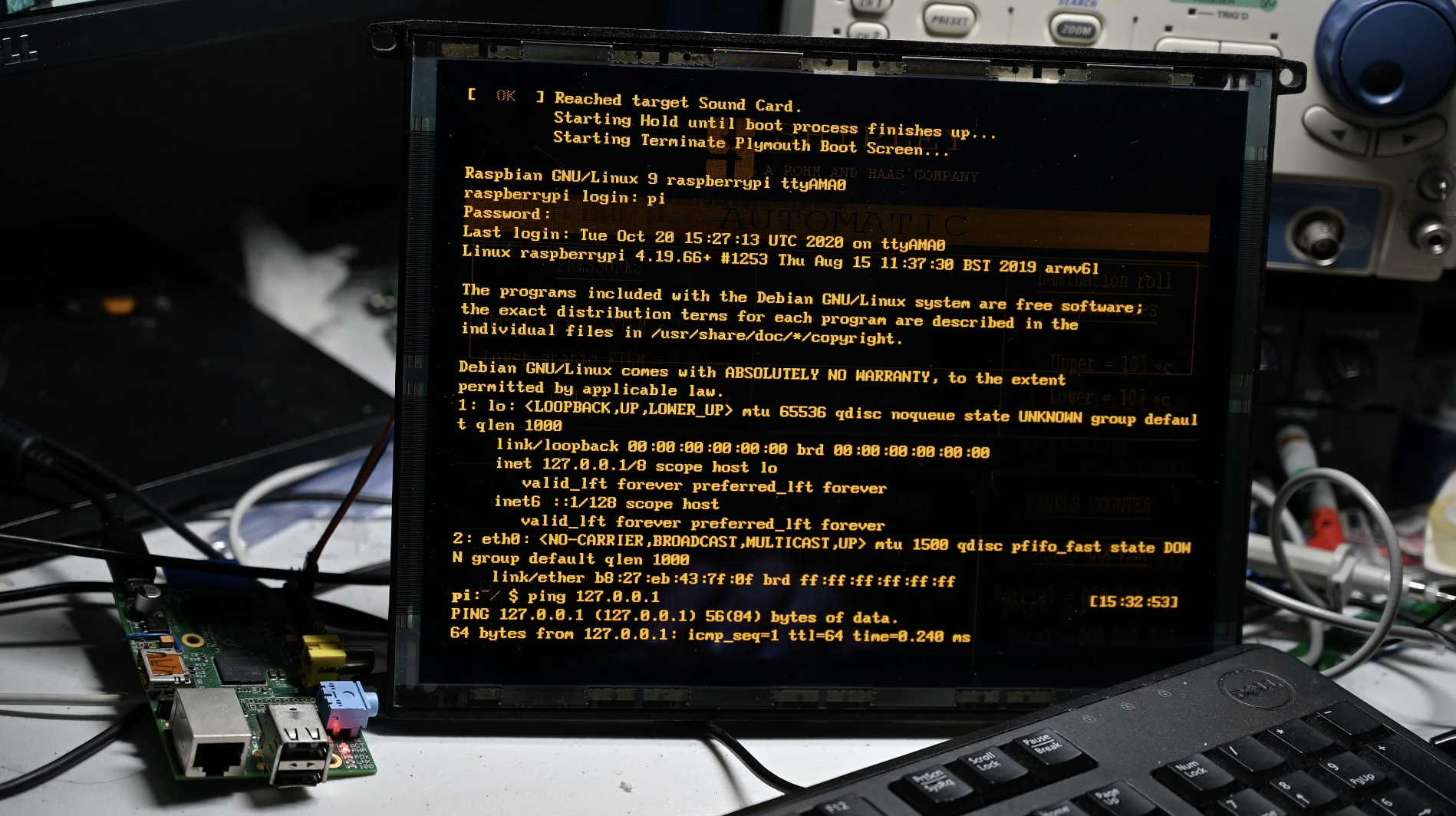
It’s a serial terminal, so there is no graphical display
This is about the end of the video. See you next time.