 James Newton
This code reads the A2D pins from the sensors, tracks the middle of the signal range, chops that into a high or low signal, and displays all that for the Serial Plotter so you can debug the setup.
The sensors in this case are nothing more than photoresistors using the internal pull up in the Arduino. (Yes, the analog pins in the Arduino CAN have a pull up enabled). The total hardware cost outside the Arduino are a pair of light dependant resistors. (!)
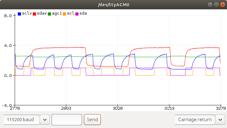
Here is a sample: The red is the data, with the green showing the cutoff point / AGC (Automatic Gain Control). You can see the slight increase on agc when the signal goes low, and the decrease when it goes high. That provides some hysteresis to avoid "bounce" or multiple edges. The blue is the clock, which also has an AGC, but it isn't shown here. Note the difference in signal levels caused by different positioning of the sensors to the screen. The yellow and purple are the resulting SCL and SDA signals. I've not yet decoded those to retrieve the data. The data is coming from this page:
https://jamesnewton.github.io/webbot.html
and the source for that page is
https://github.com/JamesNewton/JamesNewton.github.io/blob/master/webbot.html
(not the free secure web page hosting from github and the ability to access the phone camera inside the browser)
Here is the code, such as it is. Much work remains to be completed, and I will NOT have time for it. I really hope others will pickup and run with this.
/*
  ReadAnalogVoltage

  Reads an analog input on pin 0, converts it to voltage, and prints the result to the Serial Monitor.
  Graphical representation is available using Serial Plotter (Tools > Serial Plotter menu).
  Attach the center pin of a potentiometer to pin A0, and the outside pins to +5V and ground.

  This example code is in the public domain.

  https://www.arduino.cc/en/Tutorial/BuiltInExamples/ReadAnalogVoltage
*/

#define SDA_CHANNEL A0
#define SCL_CHANNEL A1
#define FILTER 256

  float agc0, agc1, hi1, lo1;
  float hysteresis;
  bool scl, oscl, sda, osda;
  bool pause;


// the setup routine runs once when you press reset:
void setup() {
  // initialize serial communication at 9600 bits per second:
  Serial.begin(115200);
  pinMode(A0, INPUT_PULLUP);
  pinMode(A1, INPUT_PULLUP);
  //good starting values for midpoints, highs and lows.
  agc0 = 2.0;
  agc1 = 2.0;
  hi1 = 3.8;
  lo1 = 1.1;
  hysteresis = -0.1;
  scl=sda=oscl=osda=0;
  pause = 1;
}

// the loop routine runs over and over again forever:
void loop() {
  int sensorValue0 = analogRead(SCL_CHANNEL); //clock on A1
  float voltage0 = sensorValue0 * (5.0 / 1023.0);
  int sensorValue1 = analogRead(SDA_CHANNEL); //data on A0
  float voltage1 = sensorValue1 * (5.0 / 1023.0);
  scl = (voltage0 > agc0)?1:0;
  if (scl != oscl) { //clock line changed
    agc0 += scl?hysteresis:-hysteresis; //noise suppression
    oscl = scl; //update
  }
  agc0 = ((agc0*FILTER) - agc0 + voltage0)/FILTER;
  //sda = (voltage1 > agc1)?1:0;
  if (voltage1 > agc1) { //data high
    hi1 = ((hi1*FILTER) - hi1 + voltage1)/FILTER;
    sda = 1;
  } else { //data low
    lo1 = ((lo1*FILTER) - lo1 + voltage1)/FILTER;
    sda = 0;
  }
  if (sda != osda) { //data line changed
    //agc1 += sda?hysteresis:-hysteresis; //noise suppression
    hi1 += sda?hysteresis*2:-hysteresis*2; //noise suppression
    osda = sda; //update
  }
  //agc1 = ((agc1*FILTER) - agc1 + voltage1)/FILTER;
  agc1 = (hi1 + lo1)/2;

  if (Serial.available() > 0) {
    // read the incoming byte:
    Serial.read(); //clear it but toss it
    pause = pause?0:1;
  }
  if (!pause) {
    Serial.print("sclv:");
    Serial.print(voltage0);
    Serial.print(", sdav:");
    Serial.print(voltage1);
    Serial.print(", agc1:");
    Serial.print(agc1);
    Serial.print(", scl:");
    Serial.print(scl);
    Serial.print(", sda:");
    Serial.print(sda);
    Serial.print("\n");
  }
}
Discussions
Become a Hackaday.io Member
Create an account to leave a comment. Already have an account? Log In.