James Newton
-
Stunningly Simple Telepresence
12/27/2024 at 18:15 • 0 commentsIf you have a robot that is controlled by
- seeing light and dark on some area of a cell phone screen, and
- that cell phone is using a remote meeting app (google meet, zoom, whatever...) and
- the person on the other end has a card with a white area in the middle and black on both sides
then they can drive the remote cell phone around by moving the card left and right, up and down.
That's too simple to work, right? Right?
What if you tool an old Roomba, and used the serial interface to connect a Pico, and then had a selfie stick mounted to the top with a cell phone that people on the remote end started a video call with...
-
Validation!
08/01/2024 at 01:24 • 0 commentsPeople are starting to figure out the joy of smartphone screen IO! (Irrespective of the thumbnail, he ends up using the screen, NOT the flashlight)
-
Light Block to Arduino / Encoder
04/20/2024 at 17:53 • 0 commentsI guess I forgot to share this, but... there is no reason why the light blocks can run into a standard Arduino or whatever. In fact, it reduces the parts count way way down because you can use the internal pullup resistor on an Analog input pin if you choose the right value for the light sensitive resistor.
Here is the basic idea:
https://www.tinkercad.com/things/hOrpbRnAEXa-light-controlled-pwm-motor
Note that it would be very easy to swap in an RC servo, continuous rotation or otherwise, or even a BLDC with an ESC or whatever you like. All controlled safely and securely from your smartphone.
In general, the advantage is you can get the uC to do the low level high speed timing dependant stuff. Here is a simulation of an encoder with a DC motor. It doesn't have the light based input, but it could easily be added.
https://www.tinkercad.com/things/6cn8U75jjCL-servo-from-motor-and-encoder
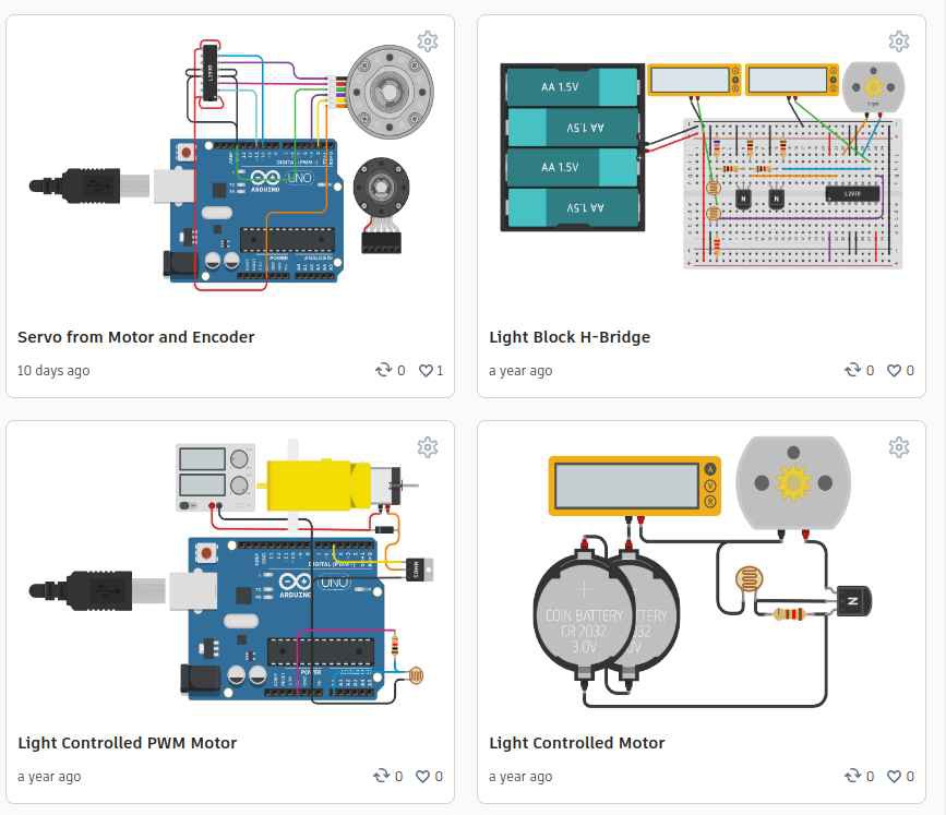
And in general, here are all the Tinkercad circuits for this project:
https://www.tinkercad.com/users/gU8oUadQpIk?type=circuitsFrom the simplest, light based circuit with a coin cell, transistor, resistor and small gearmotor, all the way up to the Arduino and Servo.
Surely this is enough for someone to actually build a robot and try it out? No? I'm really going to have to just do it myself? :sigh: ok...
![]()
-
H-Bridge Control with 2 lightblocks
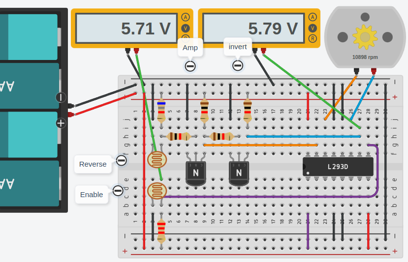
02/10/2024 at 20:14 • 0 commentsSo the prior electronics only allow forward motion. Here is a super quick design for a circuit that uses two blocks, one for "Enable" and another for "Forward / Reverse". The Enable line can't really be analog, but it can be PWMd through a few different levels at least.
You can play with it at:
https://www.tinkercad.com/things/9NsnYvF5ILO-light-block-h-bridgeby clicking Run Simulation in the upper right corner and then clicking on the opto sensors and dragging the sliders around. The position of the sliders is a bit... tricky... but you can figure it out.
One of these days I might actually build it in the real world. I need something like this the play with my twisted string actuators.
![]()
-
Another Fine Mess...
08/10/2023 at 00:53 • 0 commentsHere is another example of why I turned to light blocks on a screen to enable IOT control via web browser:
"The Goal is a web hosted app (IDE, control panel, configuration manager, etc…), served via a certificate (https) from a public domain, that talks to local (e.g. 192.168.x.x) devices via http(s), ws(s), etc… requests from the javascript in the browser. Turns out, as obvious and simple that sounds, it might not be possible." Full write up at:
https://docs.google.com/document/d/1BCrlBoenSeVpMbrXfw0HMXn-aOlhhMvPs0W7Pg-RUfo/edit -
Speeds and Feeds
08/07/2023 at 18:29 • 0 commentsBased on my own experiments and those of Aram and another friend, it looks like the speed limit on this blinking screen block to photo detector idea is about 200 bits per second. That is using an I2C type system were there are 3 transitions per bit over two block-sensor "wires".
Speed demon it aint.
But... there are several ways to work around this:
1. Parallel: Use multiple channels. There is a lot of room on a screen and photo sensors are tiny. With good alignment, it would be easy to run 8 data blocks and one clock over the bottom edge of a phone screen and so xfer byte at a time or 1600 bps. Still not fast, but, not horrible.
2. Analog: e.g. shades of gray. Probably more than 50 even. We see this in the super simple robot linked in prior log entries. This is probably what I'll use for my robot design for left and right wheel control, combined with a digital link to control reverse and other devices like a laser line or gripper. So that is just 4 blocks-sensors and should provide very responsive control of the robot.
I've never had any illusions that this thing would be fast. I did expect it would be faster than 200 bps, but even with that slow speed, given parallel and analog expansion, and the relatively slow speed of motors and physical devices, for the application of driving a robot, it's perfectly usable. The speeds of data processing and control between the phone sensors and code running on the phone are unaffected. And the data link is still there and is wide and fast.
-
Simple Simulation of Simple Circuit
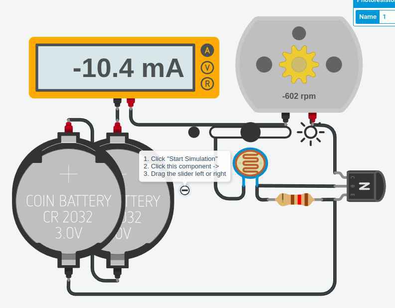
02/09/2023 at 06:00 • 0 commentsA very very simple simulation of the very simplest version of the light controlled motor circuit. One of these on the left and one on the right. The photoresistor, with tape over it to keep it from activating the touch sensors in the screen, is placed facing the block displayed on the cell phone screen. When the block is white, the motor moves. When it's black, the motor stops.
![]()
You can play with it here:
Limitations:
1. Can't go backward. (A more complex circuit might do that)
2. No speed regulation. (But the phone can use the compass / IMU to stay on course)
3. Very limited power (resistive drop through transistor, meh)
Note that the batteries shown here are just a sample. AA's or a USB battery are probably a less costly option.
KEY POINT: The cell phone controls the motor from a web page (or whatever) which has access to the phone sensors, the internet, javascript, etc... The web page can be served from any free host, like github. The javascript on that page can send sensor data to services, get back complex analysis, directions, etc... You can do voice, image, teleoperation, GPS, etc... With an old smartphone and a few dollars worth of electronics. -
More Simple Friction Drive idea
02/08/2023 at 05:30 • 0 commentsClarifying the prior post on this idea. The key is that the motor shaft is pressed own against the outside of the wheel by the weight of the cell, motor, frame, etc... The wheel is something with a rubber outside, like a fat rubber band over cardboard or an o-ring between laser cut acrylic disks. The wheel shaft fits in a vertical slot not a hole, so the shaft slides up until the top of the wheel hits the motor shaft. Motor is driven by a circuit that senses light from blocks displayed on the cell phone screen.
![]()
-
Easier with Analog?
02/07/2023 at 05:41 • 0 commentsA friend sent me a link to a very minimal version of this same idea. An analog DC motor driver looking at the light level on the screen of a smartphone and using that to drive a robot. Around. Honestly, I'm hard pressed to see why that isn't better?
https://www.voltpaperscissors.com/diy-smartphone-robot
The only advantage of using servos (which require a controller) is that the speed regulation is better.
I'm not crazy about the fact that he is using an app / photos / etc... instead of just using a web page. Also, his remote control depends on his server, but that could easily be changed. I think a local server is much better to start with especially as a gateway to the joy of simple e.g. node.js web servers or ESPs or whatever. Many security issues with an external server and apps.
Of course, the analog route doesn't really support controlling other devices, but... shrug... each new device is just a square on the screen and a simple circuit.
Also, speed regulation is really a non-issue if the program running in the phone can "learn" and watch it's accelerometers, and compass.
-
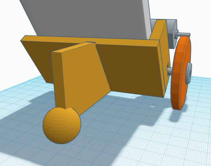
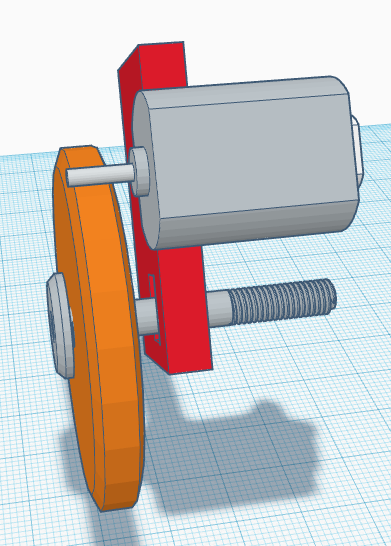
Simple Friction Drive idea
02/07/2023 at 05:37 • 0 comments(edit: picture didn't show up last time)
The idea here is that the motor shaft presses against the outside of the wheel. The wheel is something with a rubber outside, like a fat rubber band over cardboard or an o-ring between laser cut acrylic disks. The shaft actually goes all the way through to the other side (only showing half here). The red block has a slot not a hole, so the shaft slides up until the top of the wheel hits the motor shaft. The motor is connected to the red block, or to a sheet or PCB connected to that block. A PCB behind the motor also holds the light sensor, pointed at the phone screen.![]()
https://www.tinkercad.com/things/2JTX6x4Dj0k-dazzling-lappi/edit
Web Smart (Phone) Screen Blink Bot
Secure web page on smartphone safely drives cheap bot with flashes of light using internal sensors and web services.