 Stephen Chasey
After a few days of checking and finding/fixing plenty of mistakes I think I'm ready to order some boards. I panelized the sensors and adjustment pots using v-cuts drawn on a user layer. and marked the non-trace areas where it can be drilled or cut for mounting.
Now only the IR leds are on the secondary power rail. This prevents the occasional spike when the feeder activates when sensitivity is turned up - seems to be the phototransistors when they first receive power. Leaving the op amp and phototransistors on mitigates this and uses very little additional current.
I also added an "External Bus" that can be used to monitor and control the feeder with a microcontroller or SBC.
There is also a barrel jack and a USB type B connector in addition to screw terminals for power.
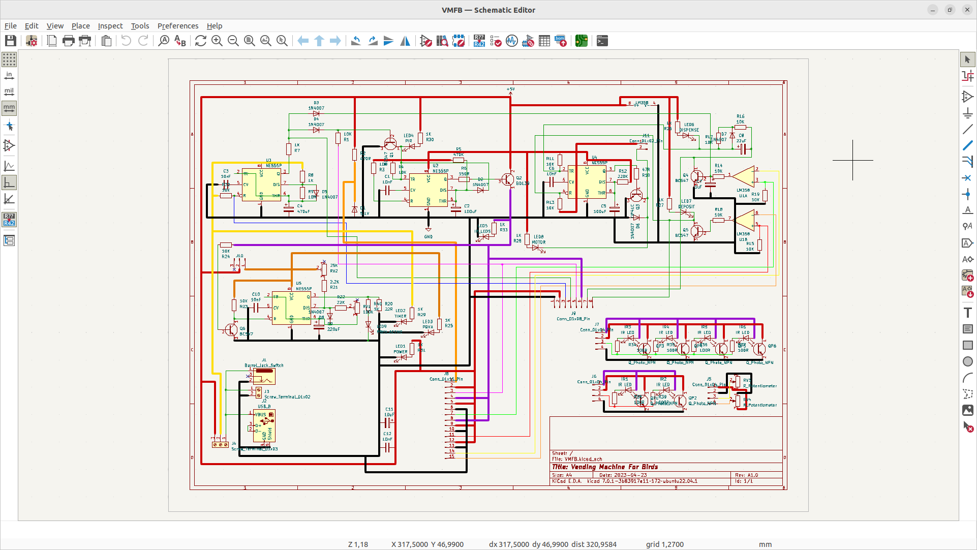
Schematic with color-coded wires - helps me with double-checking.
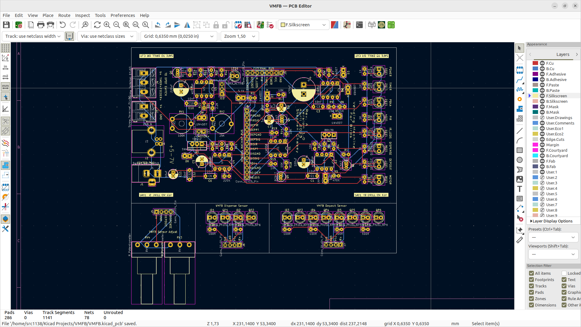
PCB with traces.
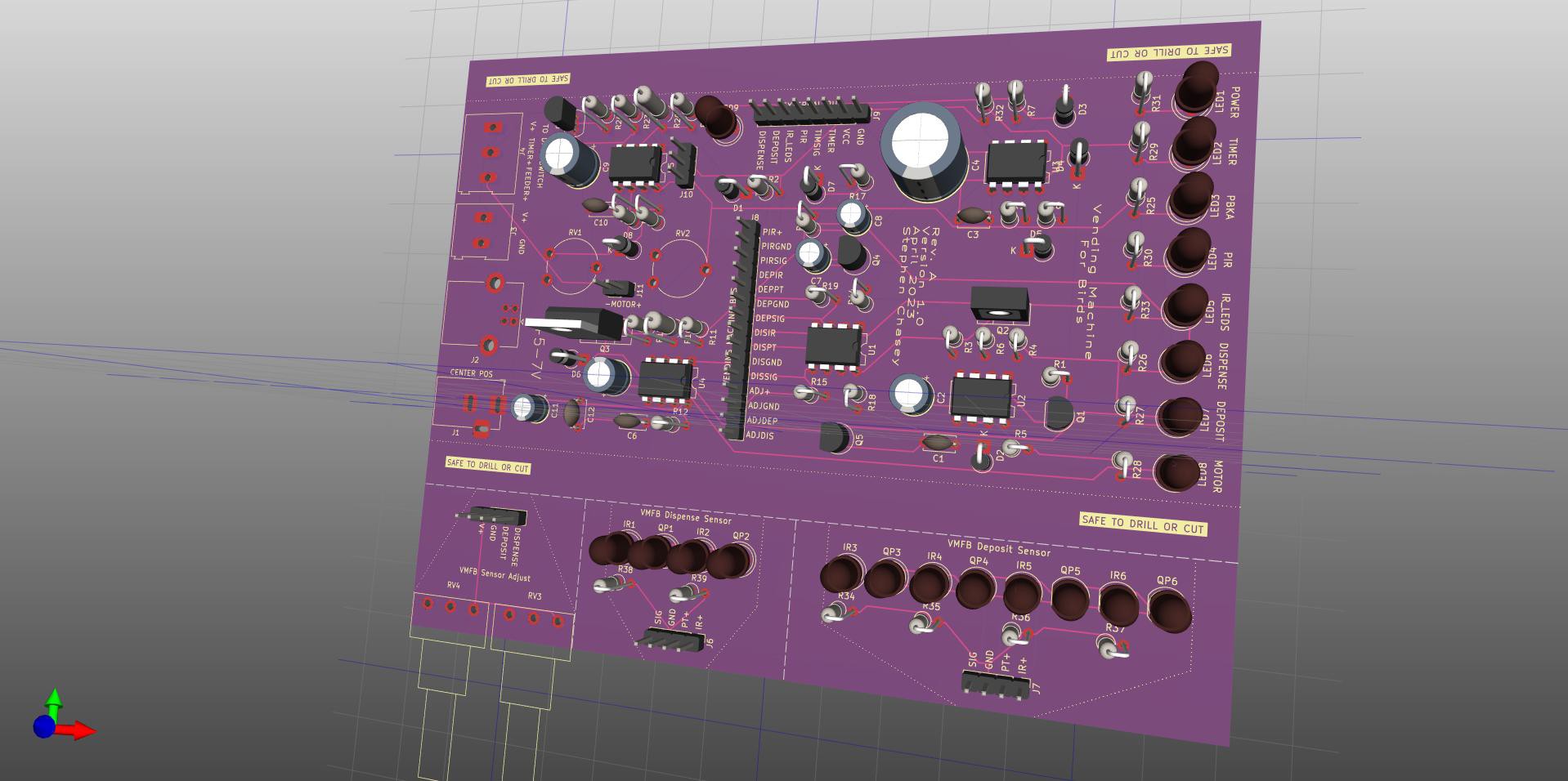
3D View (with components when models are there).
So maybe a little more checking, then I'll see if I can make my order over the weekend.
Discussions
Become a Hackaday.io Member
Create an account to leave a comment. Already have an account? Log In.