 Stephen Chasey
The latest version of the PCB I received from PCB way works as expected - I managed to fix the mistakes I made in the previous versions without creating new ones.
I made a very brief video showing the basic fuctionality here: https://cdn.hackaday.io/files/1847547904515136/20230601_233103~2.mp4
I wanted to keep it short so I could upload it to HAD (<50MB) so there are a few things I didn't demonstrate:
- timed dispense adjustable from ~5.5 to ~60 min
- power-bank keep-alive adjustable period from ~5 to ~20 sec, pulse adjustable from ~0.6 to ~1.5 sec
- inline 10uF/100K on depolit line so if the sensor gets blocked ot jammed it won't keep dispensing
- no level shifter required to monitor with 3.3V uC since it's monitoring transistor bases - PIR, deposit and dispense 547Bs are 0.7V at the base and the IR LEDs BC137 is 3.4V at the base. I may change the IR LED transistor to switch the IR LEDs to ground instread of VCC so the voltage on that base is 0.7V as well - still seems to be ok as-is, just not optimal. You probably need to use ADCs to monitor 0-0.7V though. I will test this with an ESP32 before I make any more changes here.
And some pics.
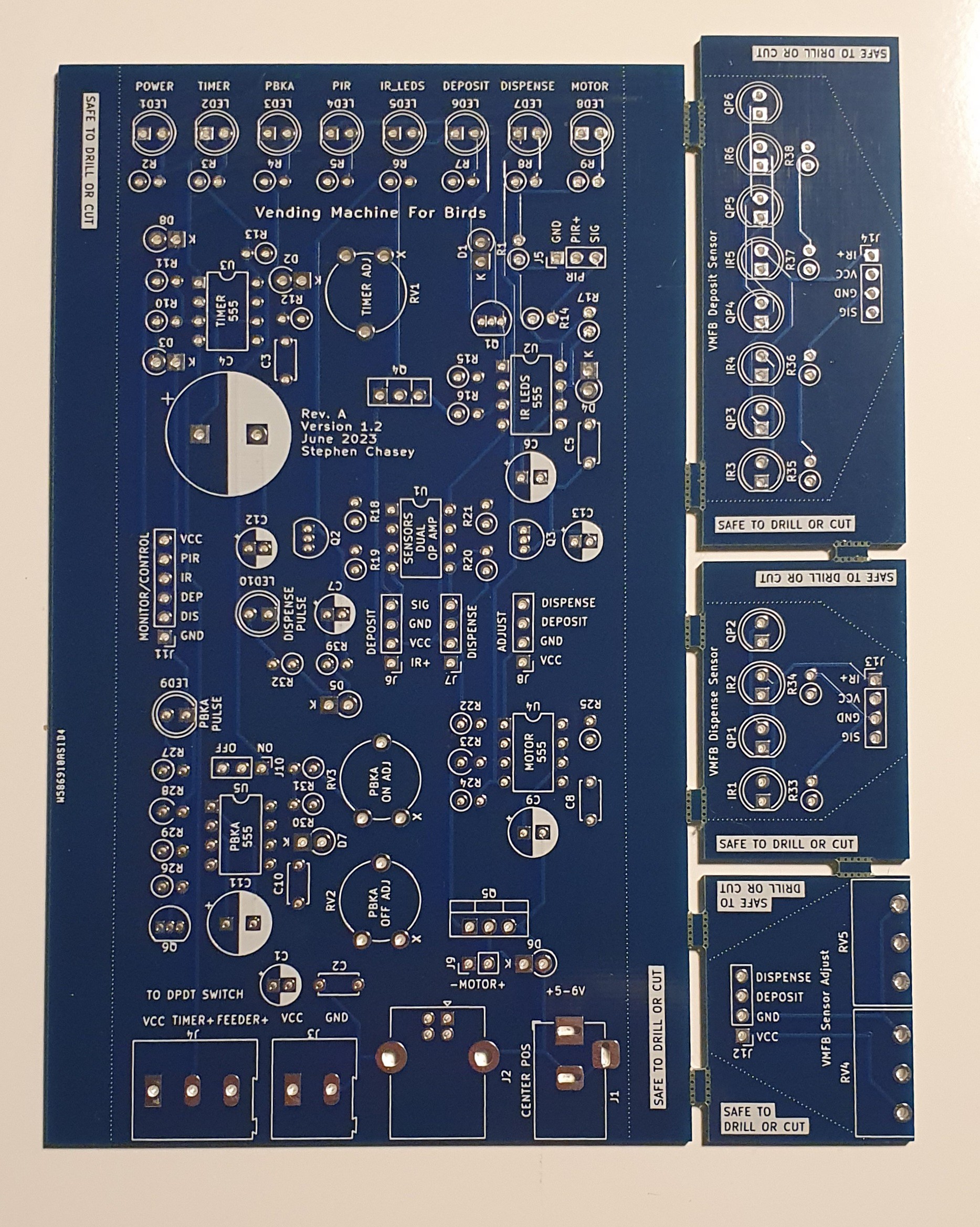
Bare board
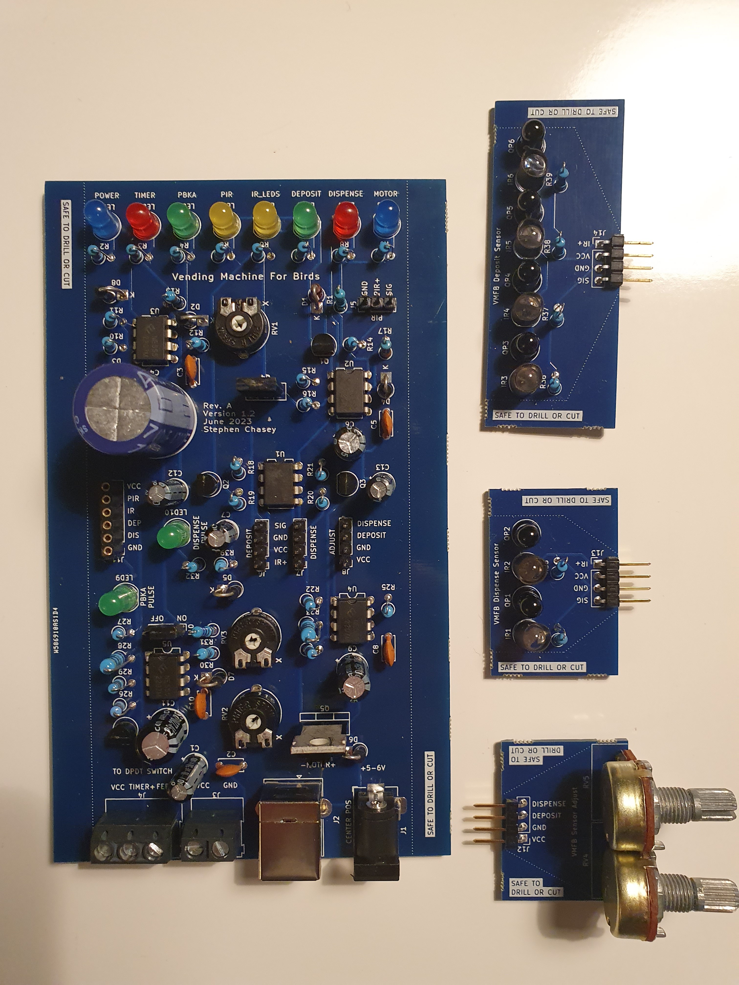
Populated board
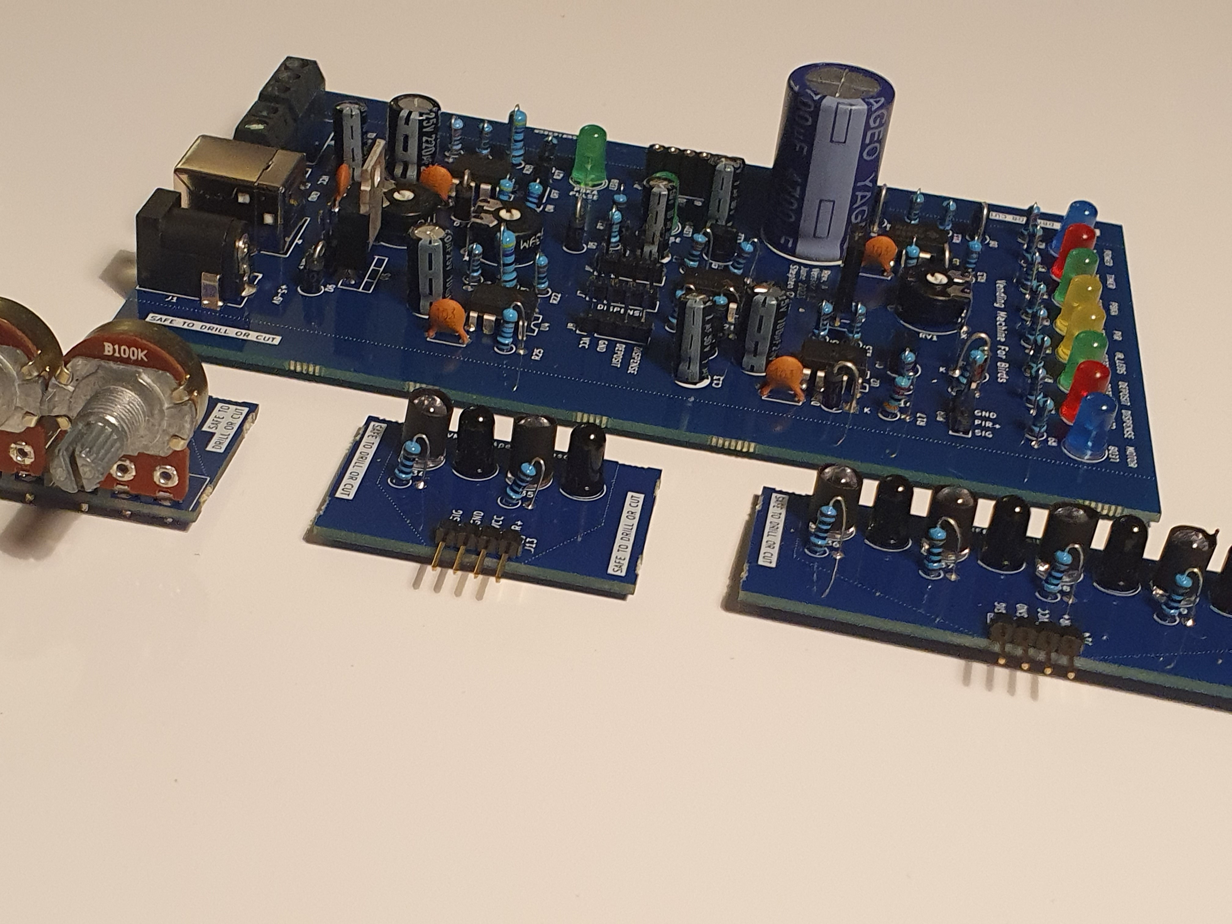
 Side view
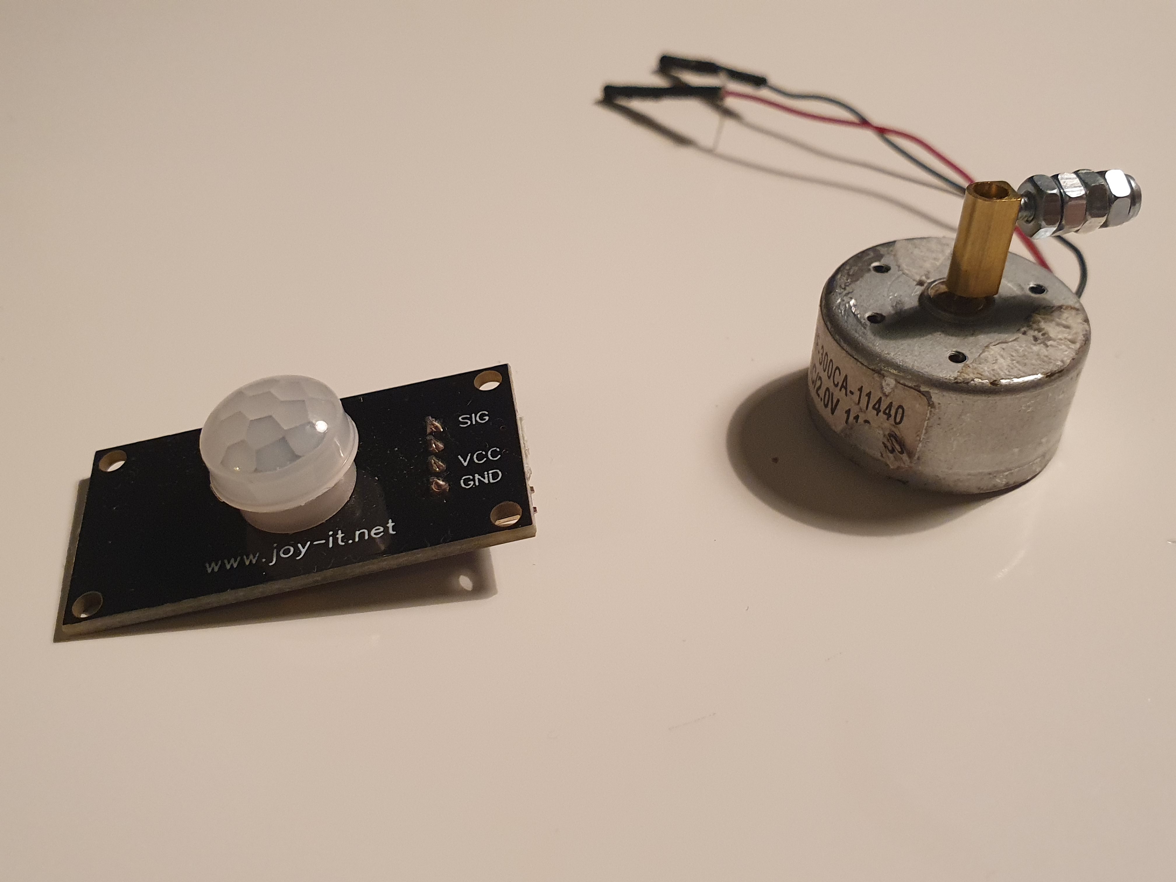
PIR and motor
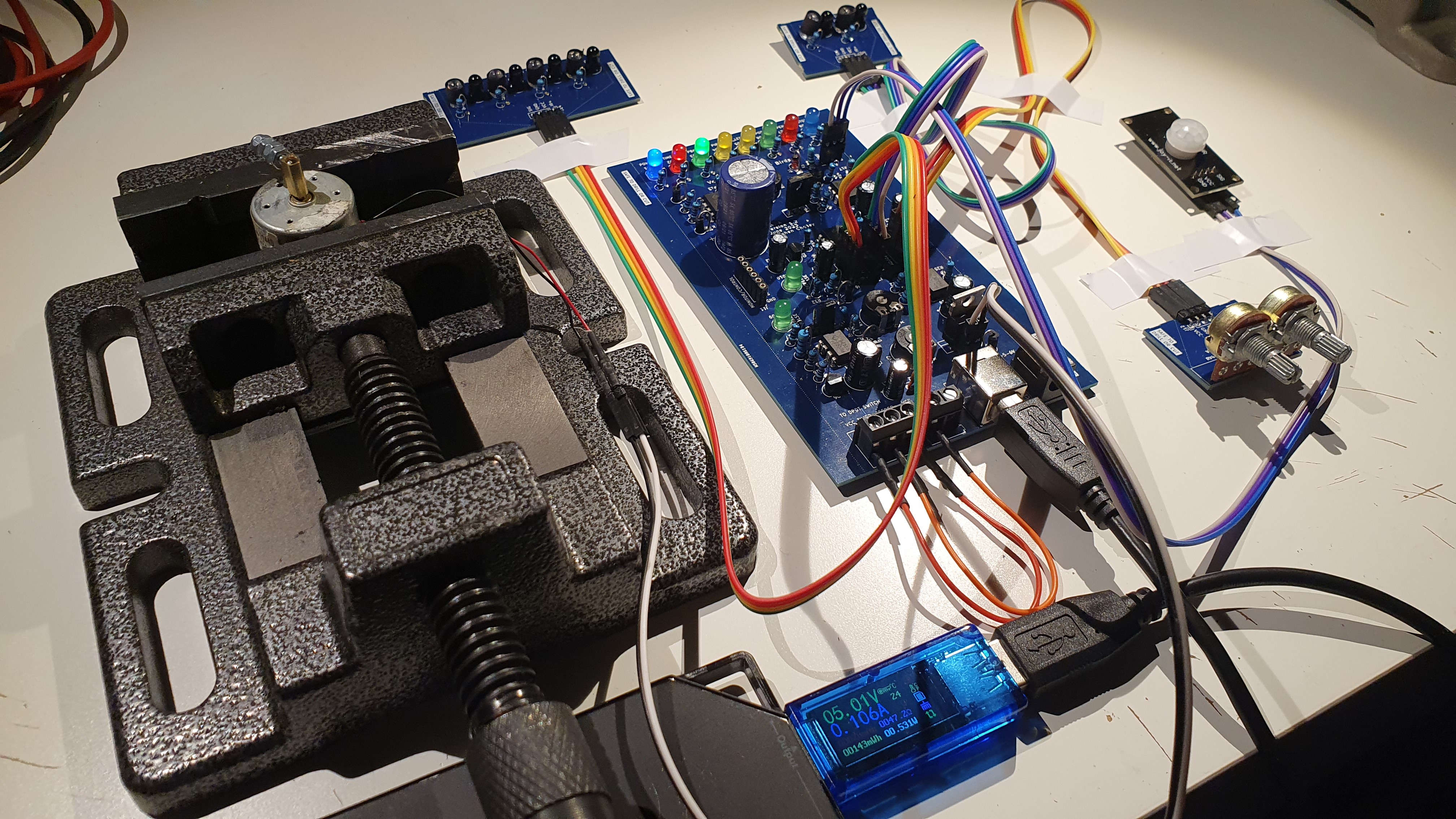
Test rig
Still mulling a few component changes - mainly putting a 22R (instead of 47R) on the 555 output that runs the motor to give it a little more current and putting a 47R (instead of a 100R) on the 55 running the IR LEDs for the same reason, though it seems to work fine with 100R. Also, the 4700uF cap could be reduced if I use a larger value pot on the timer.
I also have some new PVC joints so I can optimize the enclosure a bit and facilitate checking operation and swapping batteries. I'm hoping to "finish" the design and construction part of this project within the next few months.
Discussions
Become a Hackaday.io Member
Create an account to leave a comment. Already have an account? Log In.