-
Playing back audio using Pulse Code Modulation (PCM)
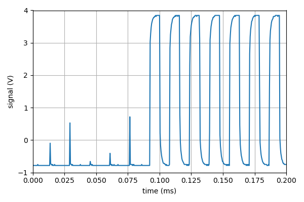
04/24/2022 at 05:18 • 0 commentsI like to think about Pulse Code Modulation (PCM) as similar to AM radio: there's a high-frequency carrier wave that you amplitude modulate with your low-frequency input signal. The amplitude modulation is done in an indirect way by letting the signal strength set the duty cycle of the carrier wave, which has constant frequency and amplitude. Duty cycle of one for maximal signal strength and duty cycle zero for minimal signal strength. After low-pass filtering to get rid of the carrier wave, the output signal then approximates the input signal. For Michael Smith's PCM library for AVR MCUs, the carrier wave is a 62.5 kHz ultrasonic square wave. Here is the measured output on Pin 11 for an Arduino clone (with the ATmega328P chip) that is running PCM:
![]()
The amplitude of the input signal is set to zero until t = 0.09 ms when it is cranked up to half the maximum value, resulting in a duty cycle of 1/2. As can be seen, some of the carrier wave is bleeding through even with the amplitude turned all the way down. I'm not sure why. [Edit: On ATmega168 and ATmega328 the timers have a minimum duty cycle of 1/256 in fast-PWM mode, as explained in an excellent blog post by @Ken Shirriff ]. The sampling frequency of the PCM library is 8 kHz, so the duty cycle can be changed every 7.8125 periods of the carrier wave (compare with the seven periods shown in the plot). The separation of time scales between carrier and signal is thus not great, which motivated the development of the active filter documented in my previous log entry. The square wave is not that impressive, one could of course to better with an NE555. However, the nice thing about generating the carrier wave on an AVR MCU is that also the modulation becomes easy to implement.
The duty-cycle modulation is done in an Interrupt Service Routine (ISR) that reads the audio-amplitude data byte by byte from flash memory. Resources are scarce, both memory and clock cycles, so it is not possible to decompress audio that uses some fancy compression scheme. With 8 kHz sampling frequency, the Nyquist frequency is 4 kHz. You can't really halve that without going from lofi to nofi, so to extend playback time the only option is to reduce the bit depth of the signal samples.
The original PCM library only supports 8-bit depth, but I've extended it to also be able to play back bit-crushed audio, with a bit depth of 4, 2, or 1. I've also made some other changes (so that avr-gcc can build and link without Arduino code and to allow playback of multiple audio samples, and multiple times). The latest version of my code can be found in the cardeaduino GitHub repo, but I'll upload the source files to this project page too.
To debug and test my code I have been using a 1 kHz sine wave generated as a wav file by SoX. The PCM library wants the audio signal in the form of an array of unsigned chars stored in flash memory. To accommodate PCM I've used a converter I call wav2h, that can also be found in the cardeaduino repo. It is based on wav2c by Mathieu Brethes. I've added bit crushing and made some other minor changes. Wav2h takes a mono, 8 kHz wav file as input and outputs a header file with a data array containing the audio samples, as well as some meta data. I've started referring to the output format as "raudio". The header file can be included in an Arduino sketch (cardeaduino.ino in the namesake repo) or in the C source for avr-gcc (cardeaduino.c).
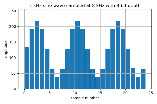
Here is what the full resolution (8-bit) "raudio" version of the sine wave looks like:
![]()
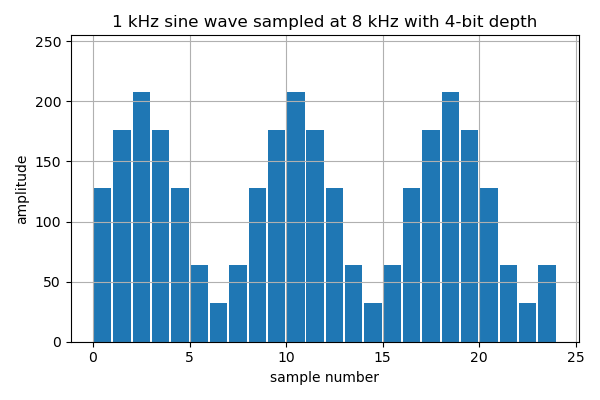
One thing I learned from this is that SoX doesn't put out a rails-to-rails signal in its wav output files! Here's the bit-crushed version, with 4-bit depth (two samples stored in a single byte):
![]()
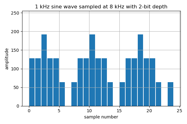
Literally 2-bit version (four samples per byte):
![]()
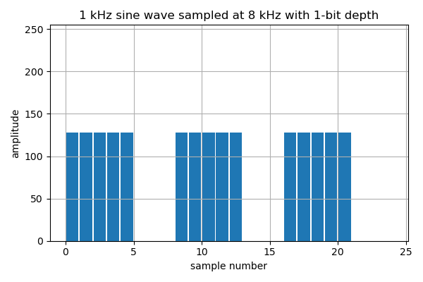
And finally the 1-bit version (eight samples per byte):
![]()
I haven't done any extensive testing yet, but tentatively I think that the 4-bit version might be generally useful for lofi. It sounds pretty similar to 8-bits, but with some pretty tolerable noise added. Two-bit might be acceptable in some cases too.
-
Sallen-Key low-pass filter with single-BJT emitter follower
04/16/2022 at 05:44 • 0 commentsThe raw PCM signal on Pin 11 is ugly. The unfiltered "carrier wave" causes loud ultrasonic noise at 62.5 kHz (and 187.5 kHz and so on). This is just over a decade above the 4 kHz Nyquist frequency so to reduce the noise by 40dB you need a second-order low-pass filter. The time-honored approach here is to say "the speaker's inductance makes it an OK first-stage low-pass filter and the human ear will do as the second stage". For many purposes this might be true. However, even if you can't directly hear the ultrasonic noise, it interferes with the speakers ability to produce fidelitous sound.
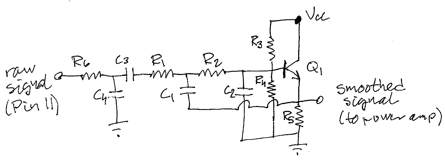
The raw signal also has much too high impedance to drive a speaker (typically 8 to 32 Ω). To kill two birds with one stone I therefore decided to use a Sallen-Key (second-order active) low-pass filter with a cut-off frequency of 4 kHz. The generic Sallen-Key topology uses an opamp with the output directly connected to the inverting input. I've always wanted to try to use a slightly less ideal gain device for this purpose: a single-BJT emitter follower. The emitter then becomes the inverting input / output and the base corresponds to the non-inverting input. Here's the schematic:
![]()
The Sallen-Key filter consists of Q1, R1-R5 and C1-C2. To the left of the coupling cap C3 there's a passive filter (R6 and C4) that I'll probably get rid of in the next version. Q1 is an 2SC1815 NPN BJT, chosen because it has the highest gain (β ≈ 700) of the transistors I had at hand. Values of the passives are chosen to implement a Chebyshev low-pass filter with cut-off frequency 4 kHz and 1dB passband ripple: R1 = R2 = 4.7 kΩ, C1 = 22 nF and C2 = 4.7 nF. The voltage divider used for biasing has resistor values R3 = 3 kΩ and R4 = 4.7 kΩ, respectively. The emitter resistor R5 = 2.2 kΩ. The coupling cap C3 = 10 μF and for a passive low-pass filter cut-off frequency of 4 kHz, R6 = 4 kΩ and C4 = 10 nF were chosen. VCC is the regulated 5 V from the Arduino Uno clone. I don't use the Arduino IDE, so don't shame me for buying clones.
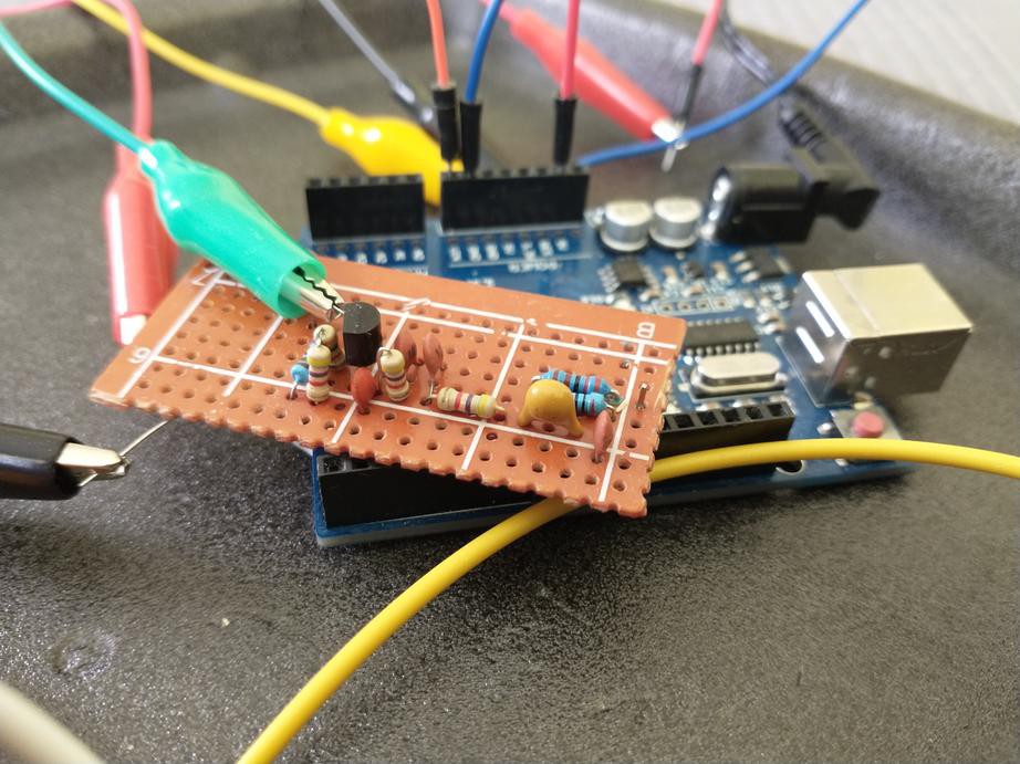
Here's the circuit on a half-finished perfboard "shield":
![]()
For C1 i used two 10 nF caps (I'm out of 22 nF) and for R6 I for some reason used (2.2 + 2) kΩ (a 3.9 kΩ resistor would have been fine). The circuit underwent some tinkering on a breadboard on my desk last fall and my notes are not exactly complete, but I remember that I was satisfied that the filter was reasonably optimized when I put it on the back burner. I recently migrated the circuit to perfboard without making any other changes.
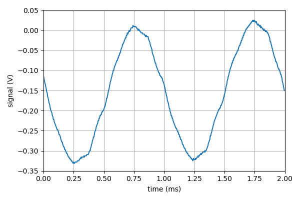
Here's what it does with an 8-bit, 1-kHz sine wave from Pin 11:
![]()
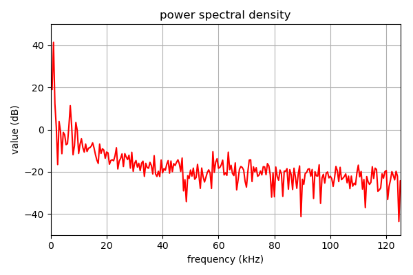
Not a perfect sine wave, but at least the distortion is symmetric. Here's an FFT of the same signal:
![]()
The strongest harmonic is the 7th one, 30dB below the fundamental, the 3rd and 9th are about 36dB below. The even harmonics are weak, consistent with the symmetric distortion. Whatever is left of the carrier wave at 62.5 kHz is suppressed by at least 50dB, which is probably more than needed, but I will test that hypothesis at some point.
Storing and playing back lofi audio on an MCU
Software and hardware for storing 8-kHz, 8-bit (or less) audio on an AVR MCU, and playing it back