 Christoph
I was asked if the probe can be used below 100 kHz. So I took one of the older ones I had around and had a look at it with the scope.
- Input to the probe: Signal generator, sine, 5 Vpp into 50 Ohm, at varying frequencies starting with 1 MHz and then from 100 kHz down to 50 kHz in 10 kHz steps.
- Output to the scope, terminated with 50 Ohm, scope set to 20x
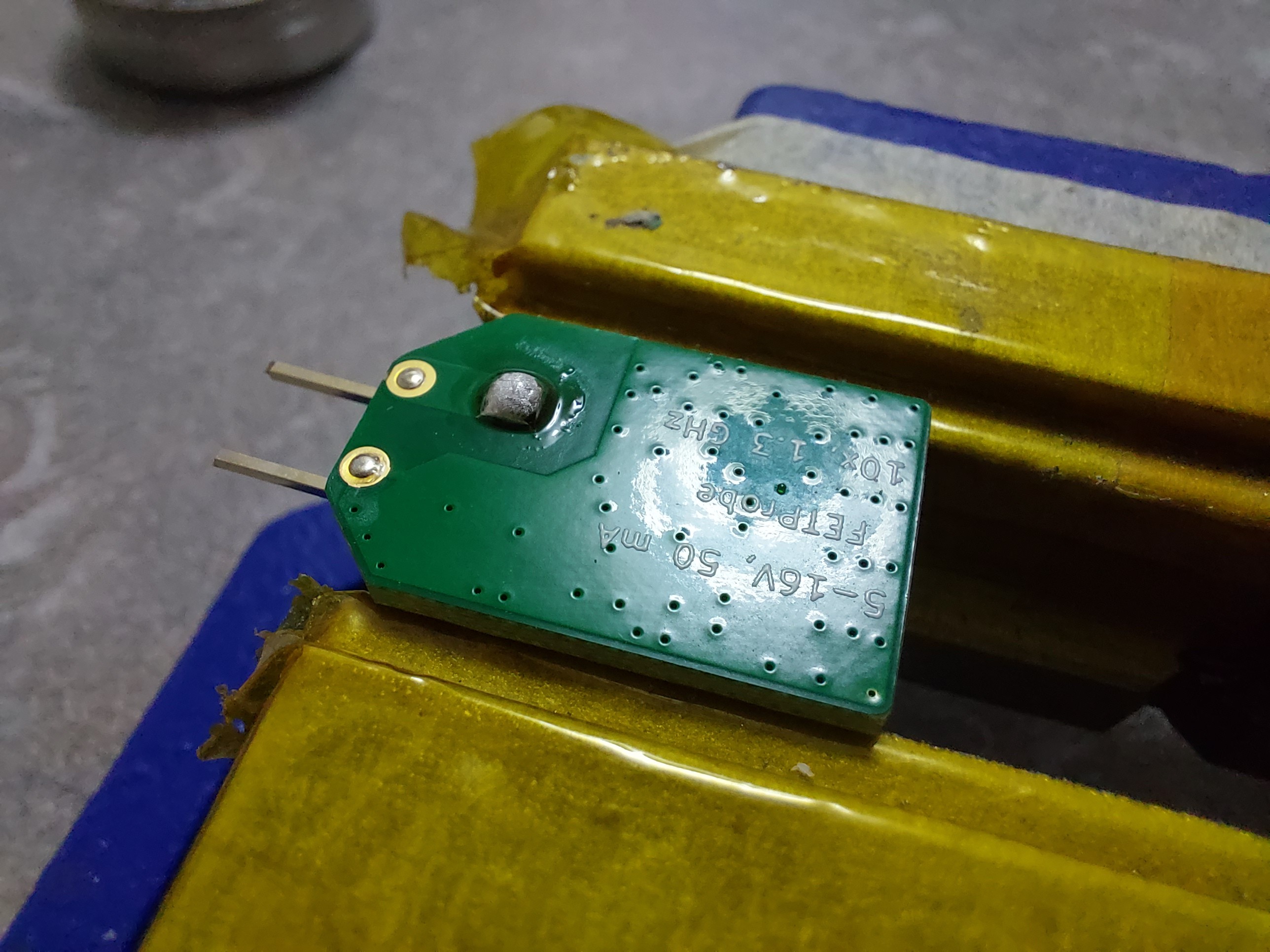
- Then another round with the input cap enlargened by solder-blobbing it.
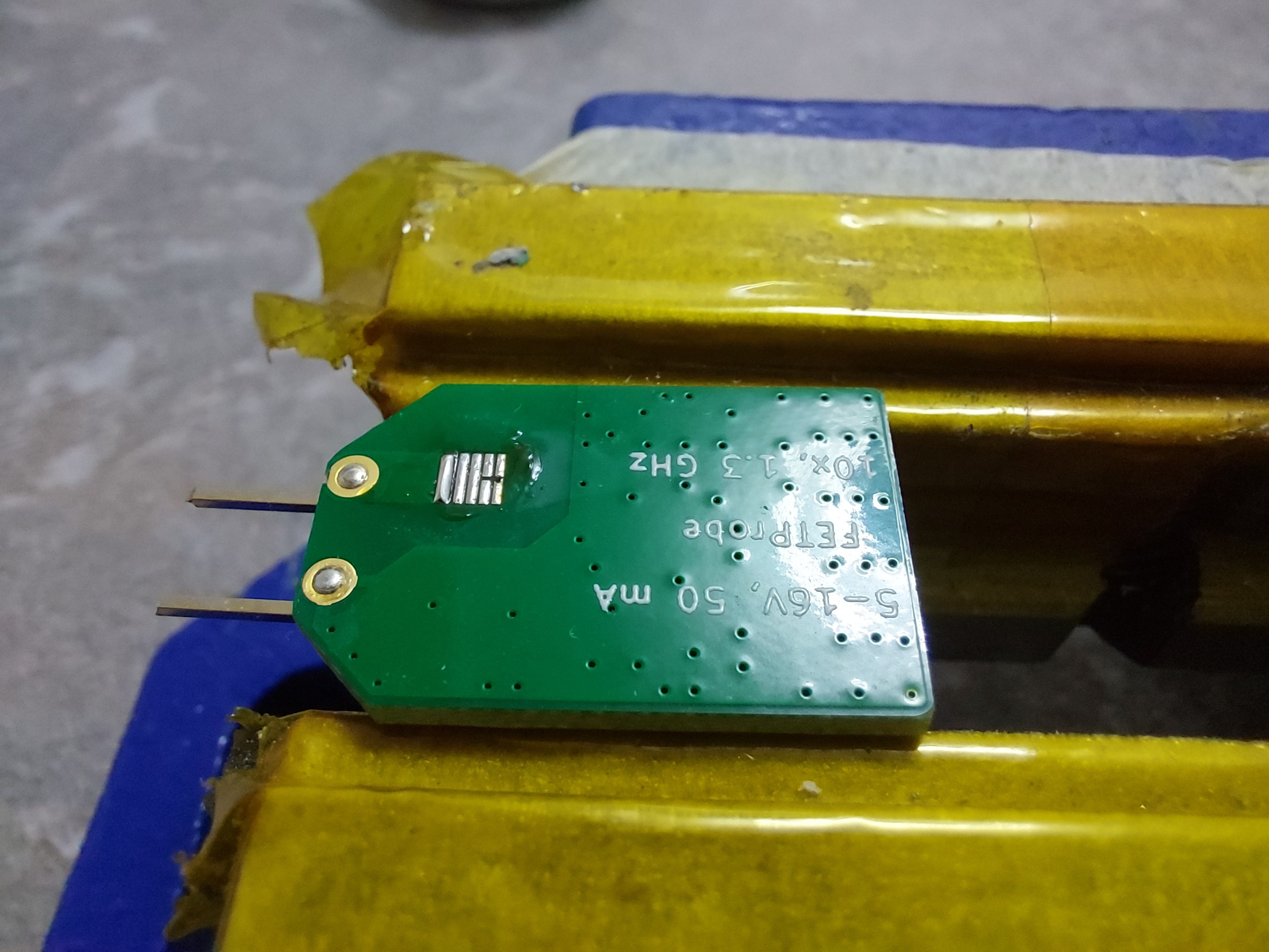
Before:
After (modified):
Result table:
So with the larger input cap the attenuation at low frequencies is around -25 to -26 dB, as desired. However, input capacitance is somewhat larger (but still low - but I don't know how low exactly).
Discussions
Become a Hackaday.io Member
Create an account to leave a comment. Already have an account? Log In.