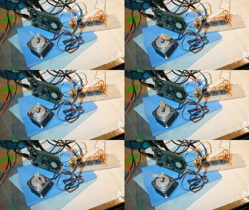
The stepper motor is spinning!

In the firmware, a timer interrupt triggers the next step of the motor. When this happens, the HAL toggles the 4 pins in a marching sequence.
The timer configuration uses HCLK, PSC, and ARR to get the frequency. To calculate these values, I made a spreadsheet. The green cells are values to be input. This means the prescaler and desired output time are modified. The auto-reload register value is calculated.
To adjust the speed dynamically, the timer’s ARR value will be changed in the code.
The motor driver electronics is a DRV8833. In the above demo it was powered by 4V @ 0.3A.
There were some troubles while making this work, in the end relating to loose connections. The solution was to add solid core wire to the stepper motor cables, which then plug in to the breadboard. Once we make a pcb, screw terminals will be used to reduce that problem.
The next step for firmware is implementing the custom stepper driver into the interrupt and writing the supporting methods.
Stay tuned for the next update which will cover an idea for the next experiment prior to the next Generator prototype iteration! Spoiler alert - it surprisingly involves a trip to a fabric store?!
 EK
EK
Discussions
Become a Hackaday.io Member
Create an account to leave a comment. Already have an account? Log In.