 EK
EKThe next experiment will place the wheel onto two freely rotating dowels. Hypothesis: the wheel will remain in place on those dowels while rotating, and while being pulled by the kite.
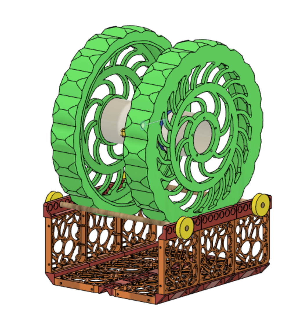
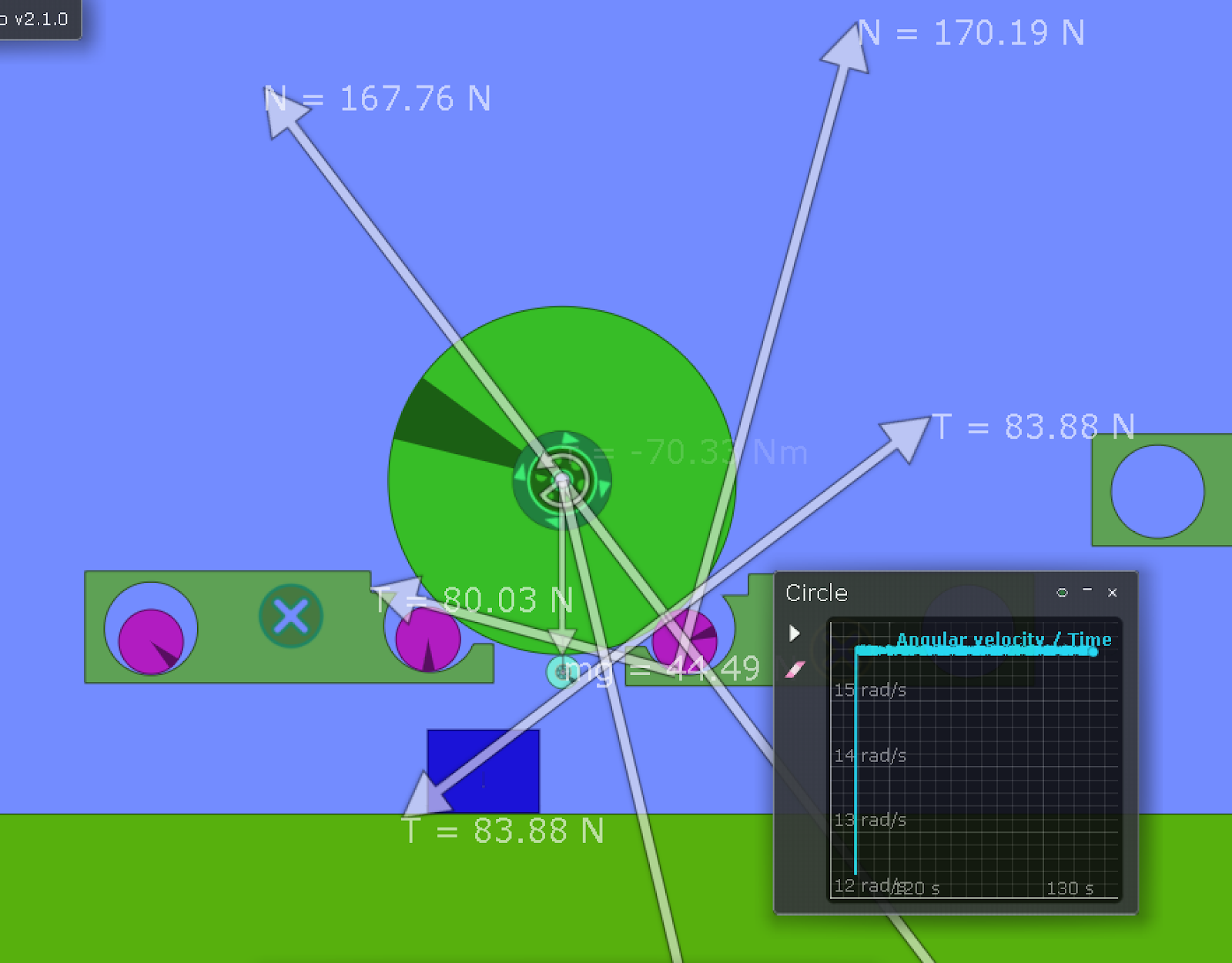
A simulation was conducted to double check the bodies rotate as expected. The smaller light-blue wheel below depicts a possible generator location.
This experiment will address a few unknowns:
- Spacing of the dowels to support wheel
- Angle of the line that would cause the wheel to ‘pop’ off the dowels
- Are the dowels able to freely rotate, or will they need ball bearings?
- Does it require a lot of force to spin?
- Are the indented grouser designs problematic?
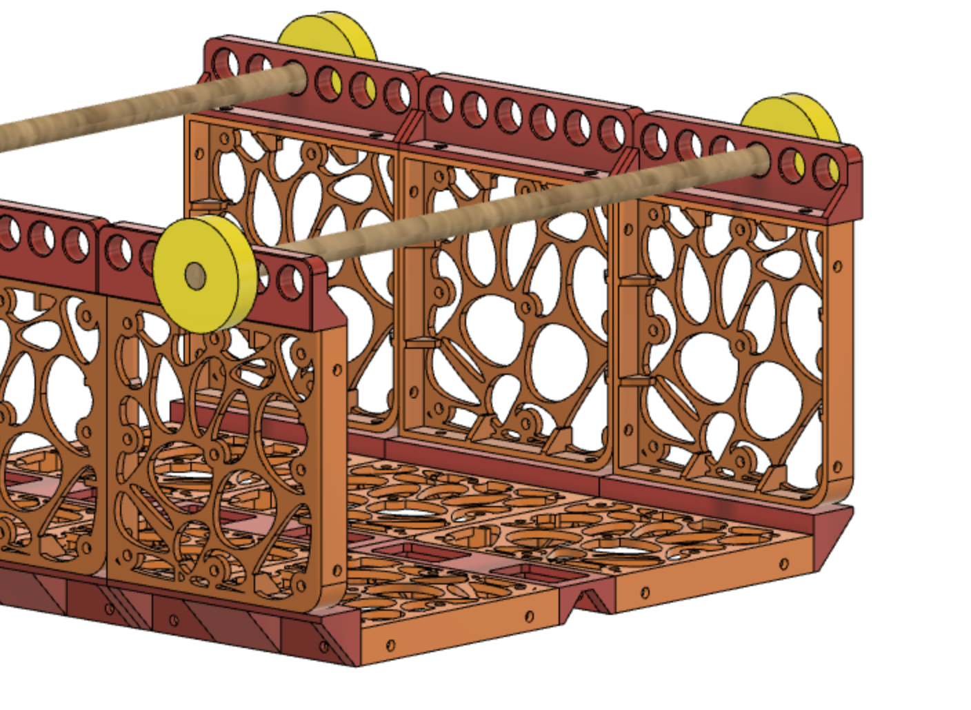
The structural tile pieces are re-used from a different project (Bowie the robot).
The next step will be to 3D print the extra pieces, assemble, and test!
Discussions
Become a Hackaday.io Member
Create an account to leave a comment. Already have an account? Log In.
This somewhat reminds me of Doubly-fed electric machines which are often used in windmills. however they seem to use gears not wheels which would add a lot wheel-slip to your system. Examples of something similar are the Fontaine and (my personal favorite) a literal pyramid scheme in more ways than 1 the Holman locomotive.
either way interesting project. perhaps some tinkering with the slip rings of the generator could offer some more insights or inspiration.
links: https://static.wikia.nocookie.net/locomotive/images/8/83/Abdill20Fontaine20a.jpg/revision/latest?cb=20150719172432
http://wx4.org/to/foam/Holman/images/Holman_Soo6.jpg
https://en.wikipedia.org/wiki/Doubly-fed_electric_machine
Are you sure? yes | no