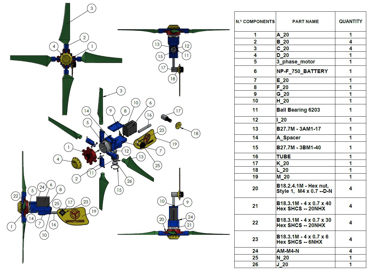
-
1STEP 1: DOWNLOAD AND PRINT ALL STL PARTS OF THE ASSEMBLY
In this video I show you a summary of how I executed the steps for the construction of the WINDTURER-P4 Prototype
Instructions and Materials List for Prototype 1 can be found here
https://www.instructables.com/HOW-TO-MAKE-a-PORTABLE-WIND-TURBINE/You can download the STLs from here in the FILES section. The most up-to-date files are published under the prefix WINDTURER-P4. These files include all improvements made since Prototype 1.
I have also included the files (STEP_IGES_X_T_3MF) in case you want to take a closer look at the assembly or change something, depending on your interests and needs. If you need any special type of file format let me know and I'll see if I can help.
I have printed my prototype on ASA filament, specifically from the manufacturer Polymaker https://amzn.to/3ryQKGe affiliate link. It is recommended that the 3D Printer, print in a closed space without drafts and use a heated bed at least 90 degrees celsius with some glue or lacquer for printing. I printed my pieces at 250 degrees celsius. PETG will likely work as well, though I haven't tested it. PLA should be discarded because it has very low adhesion between layers and on very hot days the pieces can deform.
I have included a zip file of my CURA-GCodes , in the files section for you to analyze how the pieces were printed. The layer thickness was 0.2 mm in all cases. I used a Longer LK4-PRO printer with a 0.4mm nozzle.
The propellers were printed one at a time. It took about 6 hours each. I used supports and the position was as shown in the video. The infill pattern was TRIANGLE and I used the CURA software as Slicer.
Additionally you may need some accessories to fix the tripod to the ground. I have printed some from thingiverse via these links
Tent pegs: https://www.thingiverse.com/thing:2758339
Tent cord fastener: https://www.thingiverse.com/thing:3676148How to use the tent cord fastener : (https://youtu.be/w34OC063BQA)
![]()
Don't get lost with file names!
![]()
-
2STEP 2: SMOOTH OUT SOME IMPERFECTIONS THAT RESULTED FROM THE 3D PRINTING PROCESS
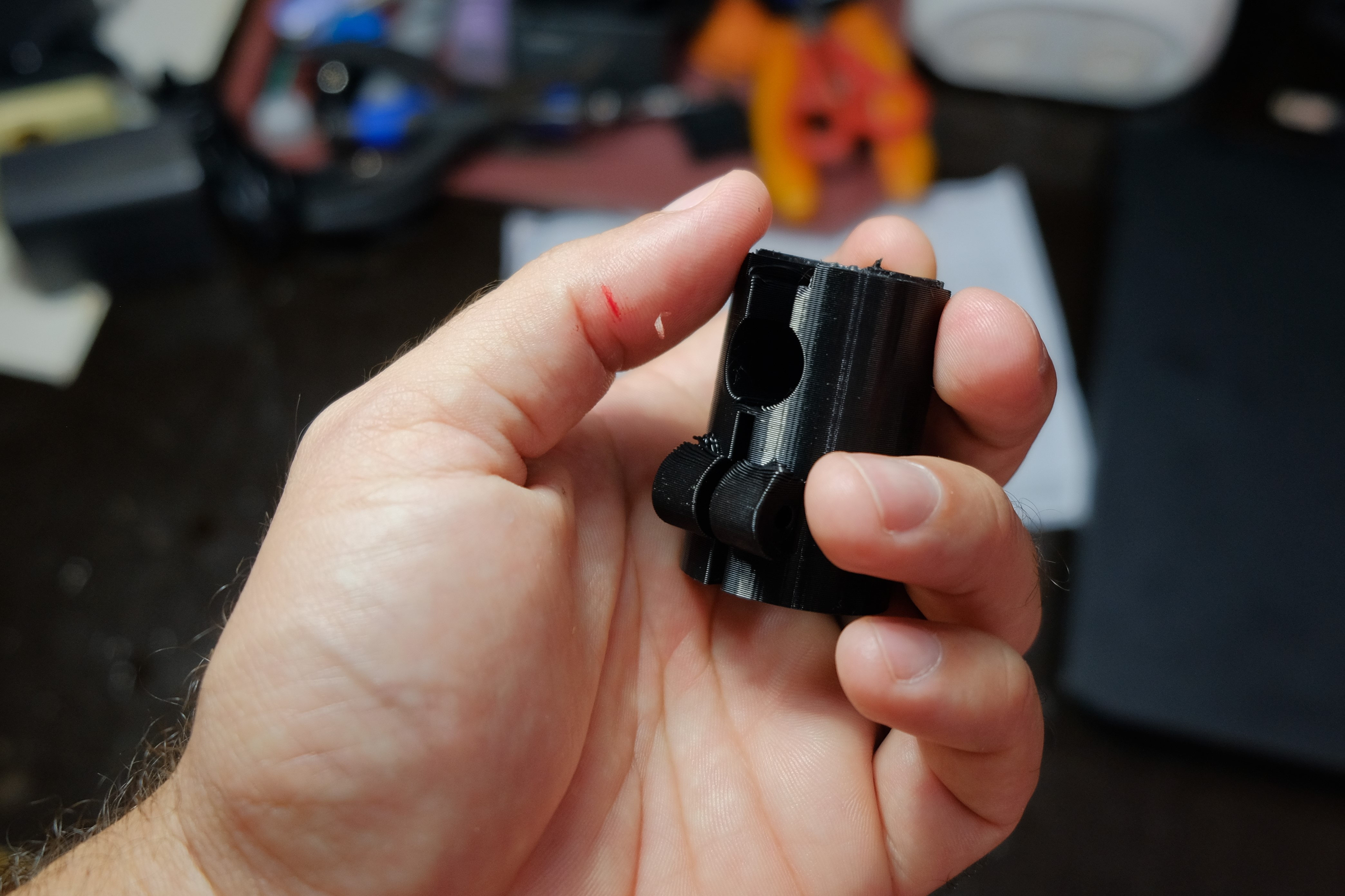
It is recommended to sand the pieces in the places where the supports were created. Also to smooth out any bumps that could affect performance or cause damage to hands when handling.
Be careful with the sharp edges of the plastic, they can cut your skin.
![]()
-
3STEP 3: SCREW THE ENDS OF THE BLADES TO THE CENTER HUB.
All the holes in the designed parts are for M4 screws. Install the bolts and nuts as shown in the video, but do not over-tighten. The ends of the blades shall be free to articulate 90 degrees. Then install a locknut so there is no chance of them coming loose.
note: Why was it necessary to make these blade terminals? Wasn't it easier to integrate the blades with these parts in one piece?
For several reasons it was designed this way:
-This makes it possible to change the angle of attack of the Blades for different scenarios and experiment for better performance.
-It makes it possible to make optimization changes to the blades from QBlade and would also result in blades compatible with the rest of the assembly. In Qblade you cannot model the Blades, the software creates them but you cannot freely create shapes.
-Also by doing it this way you can take advantage of the maximum height of common Ender 3 type printers. -
4STEP 4: STICK THE BLADES INTO THEIR POSITIONS
Put some epoxy glue inside the cavities of the Blades ends, try to cover the inner walls. Insert the Blades as shown in the video, ensuring that they are inserted all the way.
Before the glue dries and immediately after executing this step, place the central HUB with its Blades installed on a horizontal surface, as shown in the video. When turning the Blades you must ensure that the pointed back of each Blade slightly touches the horizontal surface. Once this happens, let the glue dry for at least 5 hours.
-
5STEP 5: GLUE THE MOTOR TO THE CENTRAL HUB
Clean the external part of the rotor of the electric motor (generator) with alcohol or another degreaser. The transformations necessary for this generator are declared in this LOG 11:
https://hackaday.io/project/185070-3d-printed-portable-wind-turbine/log/211015-prototype-3-rejected
Once the rotor is clean and dry, place some epoxy glue on the surface of the rotor as shown in the video. Gently slide the generator into the Hub cavity for this purpose. Let dry for at least 5 hours.
-
6STEP 6: ELECTRICAL CONNECTIONS WITH THE FULL BRIDGE RECTIFIER
There are two possibilities of Full Bridge Rectifier to use in this project. The first and recommended would be to use the circuit that I designed and that you can order directly from PCBWay, following the link that appears in this LOG:
https://hackaday.io/project/185070/log/209265-rectifier-circuit-capacitor-ready
With this Full Bridge Rectifier you will obtain better efficiency since it is based on Schottky diodes with lower conduction losses. However, it makes this project more expensive and requires you to buy the components separately and assemble them. You can also order the assembly by https://www.pcbway.com/ and with this you guarantee quality.
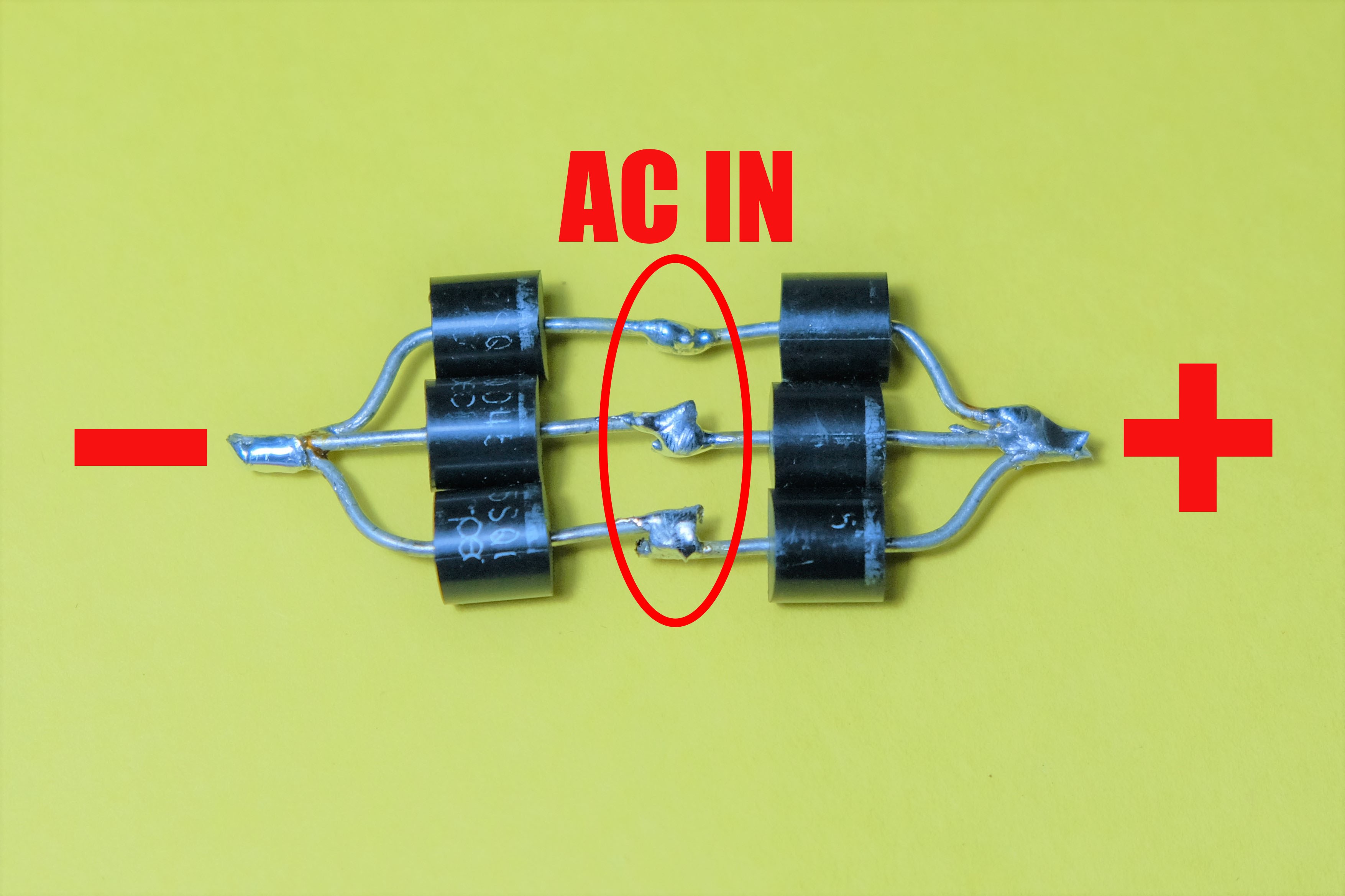
A simple way to make a three phase full wave rectifier is shown in the picture below
![]()
Another option is to buy a small size three-phase full bridge rectifier like this https://amzn.to/3CepTnI and with it you will get a DC output.
I have decided to test the Windturer-P4 with this last option to compare the results and draw conclusions about the advantages of using Schottky diodes instead of traditional ones.
The electrical connections are very simple and are drawn on the circuit board or body of the Full Bridge Rectifier. In the signs (+ and –) the positive and negative outputs to the NP-F battery pins are obtained and in the signs ~ are the inputs from the generator. Once these connections have been made, this module must be placed inside the cavity of the central body using a double contact tape.
-
7STEP 7: SCREW-DOWN THE NP-F BATTERY MOUNTING PLATE
You are probably wondering what is the reason for this Mounting Plate to be a separate piece from the central body. I decided to do it this way for 2 main reasons. The first is that it makes the 3D printing of the central body less complex by requiring fewer supports and second, it can be easily replaced in case of damage. This part in particular is subject to constant friction when installing and uninstalling the battery continuously and that it is a serviceable part, I think that is something positive.
Before performing this step you must first install the battery safety clip. First the spring is placed, then the clip is slid into its cavity and then the Mounting Plate is screwed on. At the end the button of the clip is glued and it is verified that the NP-F battery is held firmly when installed.
-
8STEP 8: INSTALL BATTERY CONTACT PINS
The battery contact pins I used in this project were taken from an old video monitor. I have tried to buy them separately but I have not found them in the common stores. I guess I have to search better but if anyone knows where to buy them please let me know.
To complete this step place a small amount of epoxy glue in each hole for this purpose of the central body. Then with a fine nose pliers install each one in its place and then place a battery to fix them in position until the glue dries completely.
It is likely that the part of the pin where the positive and negative wires from the Full Bridge Rectifier are to be soldered has been contaminated with glue. Try to clean this part of the pins before the glue dries. Then lightly file this part of the terminals and apply a little solder. Then solder the cables from the Full Bridge Rectifier in the correct position respecting the polarity of the battery.
-
9STEP 9: SCREW THE CENTRAL BODY AND ITS SPACER TO THE GENERATOR
Using the bolts declared in the material list, bolt this assembly to the generator. While performing this step, it is recommended to use some type of silicone sealant in the joints to ensure that no water enters the interior cavities of the central body.
-
10STEP 10: GLUE THE TAIL PIPE AND INSTALL THE REST OF THE ASSOCIATED COMPONENTS
The tail tube and associated components should be glued so that the tail is parallel to the lateral plane of the central body. The tail is fixed by 4 screws to the part (L) of the STL files. When folding and unfolding the tail should not interfere with the rest of the assembly.
 adriancubas


Discussions
Become a Hackaday.io Member
Create an account to leave a comment. Already have an account? Log In.
hello is there any upelate regarding the motor? Thanks
Are you sure? yes | no
Hi, I am student of final year in mechanical engineering.And working on small portable wind turbine in final year project.kindly give the blade design specification on Q BLADE that I can work on this project
Are you sure? yes | no
How is your project going? Has this helped you in your research? The files are ready. Any questions ask me. Cheers
Are you sure? yes | no
Very nice project! do you have more details about the components assembly and eletronic assembly?
Are you sure? yes | no
I am writing the steps. In a few days I will finish them. Stay tuned!!! Thanks for your comment
Are you sure? yes | no