Following a procedure similar to the electrical measurements that I have made to the previous generators (motors), I present below the results that I obtained with the Prototype 4 generator.
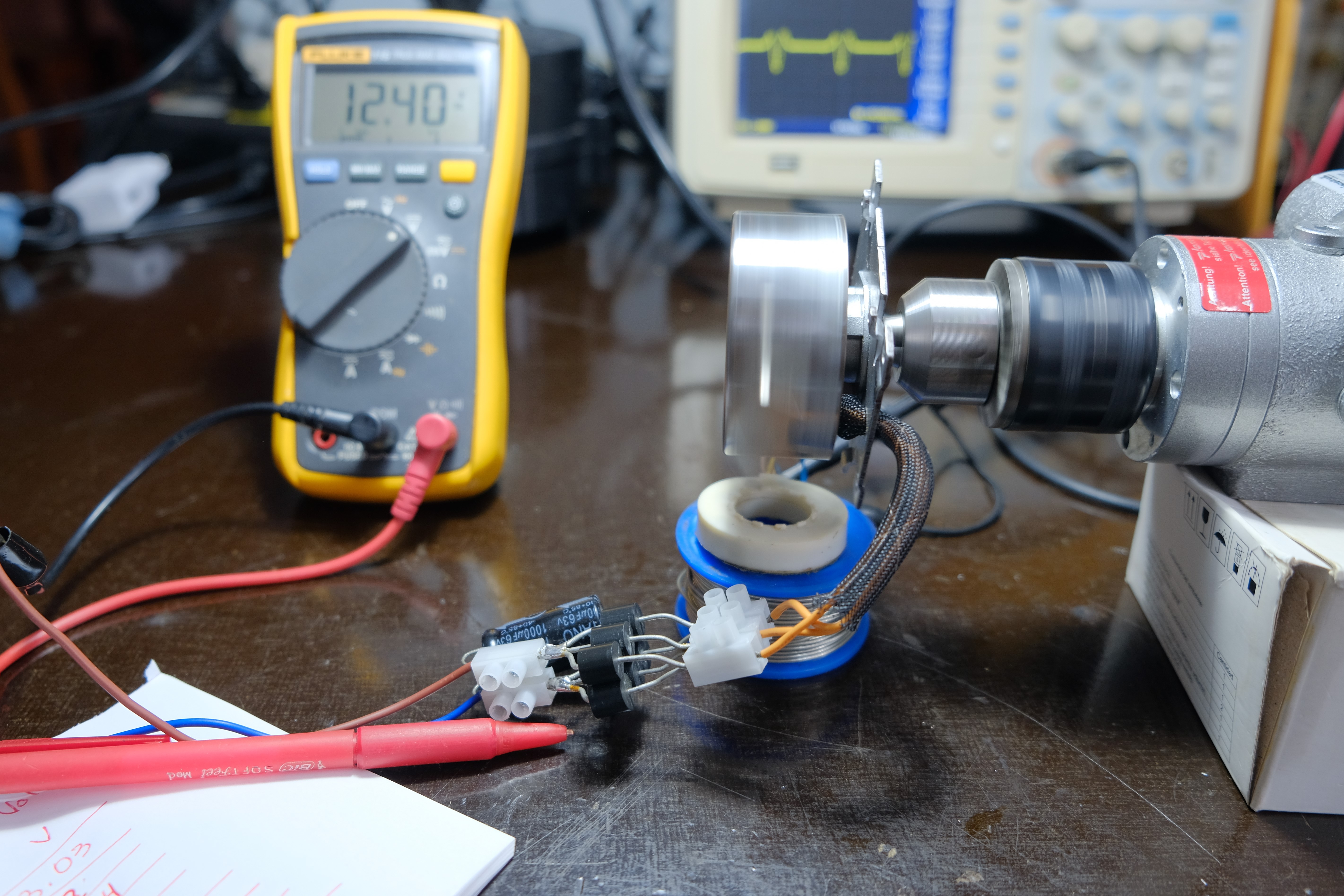
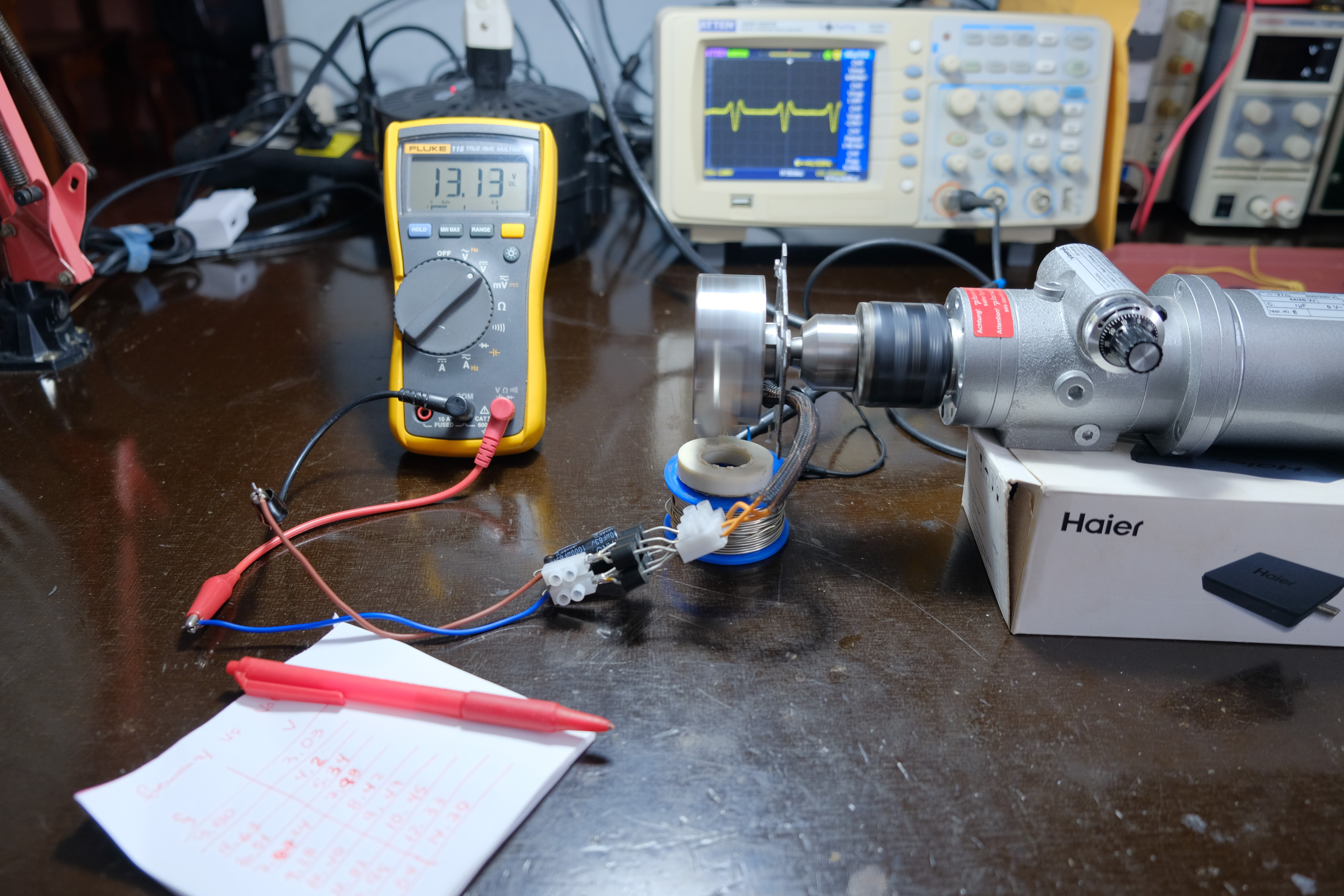
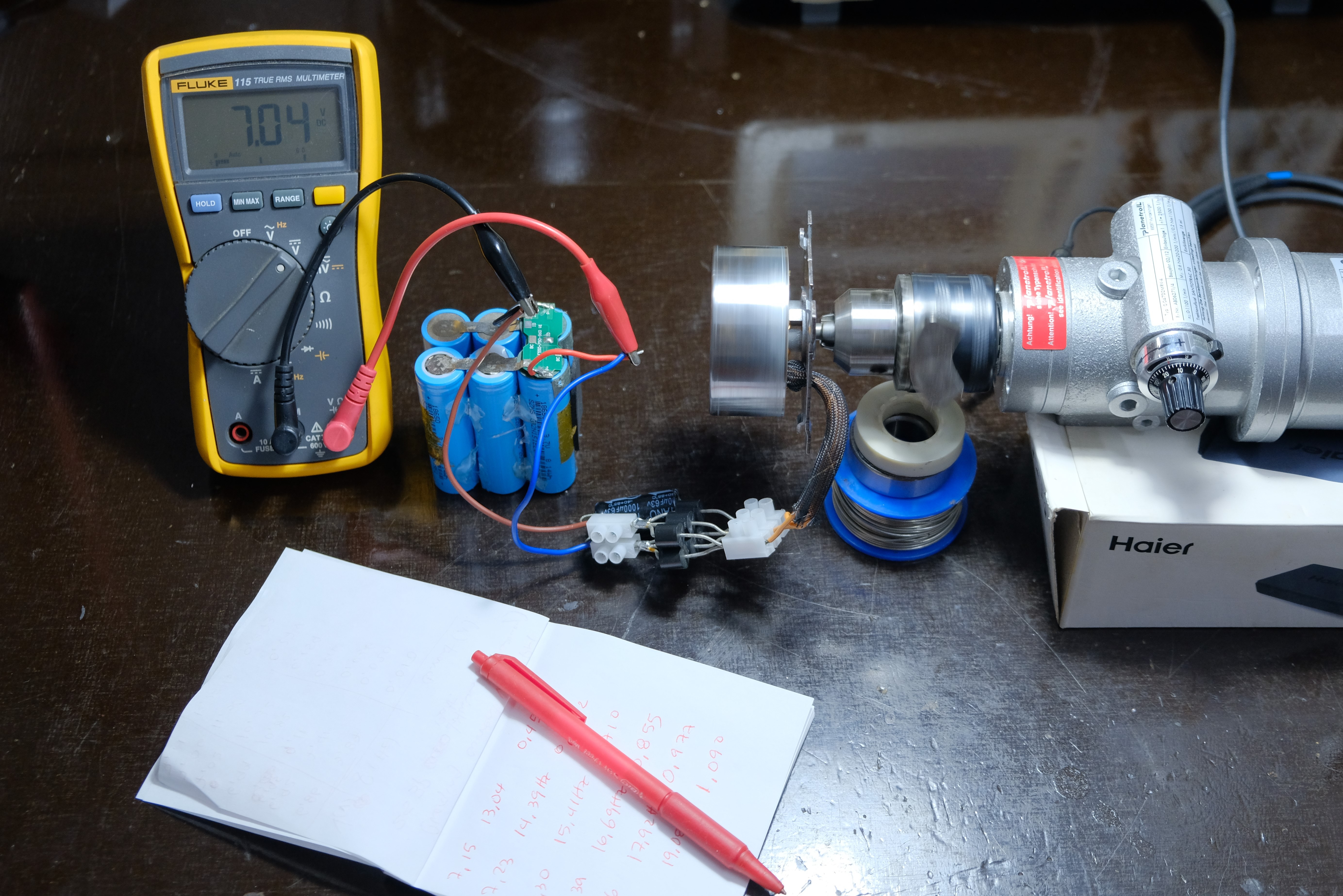
I coupled the P4 generator to a three-phase electric motor whose RPM was varied with a VFD (Variable Frequency Drive). Using an oscilloscope with a magnetic probe, I accurately detected the rotational frequency and thus the RPM at which the P4 generator was rotating. Measurements of the relationship between open circuit voltage vs. RPM, short-circuit current vs. RPM, as well as charging current for 18650-type lithium batteries in 1S2P and 2S3P configuration, respectively, vs. RPM were made.
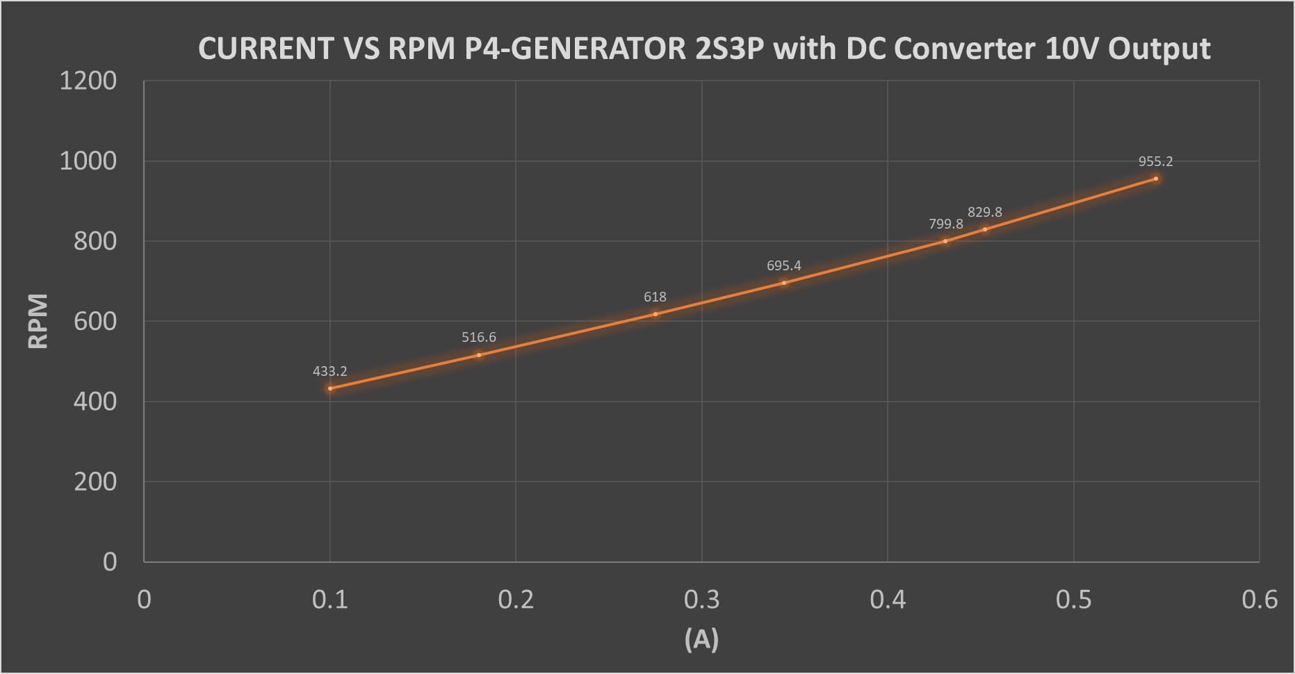
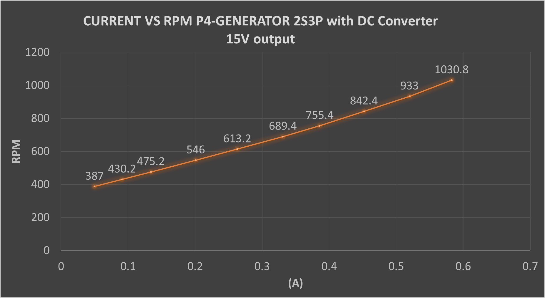
A DC Boost-Buck Converter type converter inserted between the generator and the batteries was also used to see if there was an increase in the charging current.
During the experiments and measurements carried out, the following questions were answered
1- What is the electrical resistance value of the motor windings?
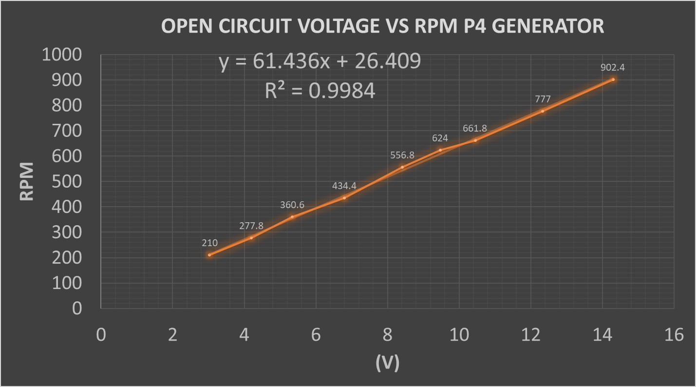
2- At how many RPM of generator P4 is 1V (kV value) obtained?
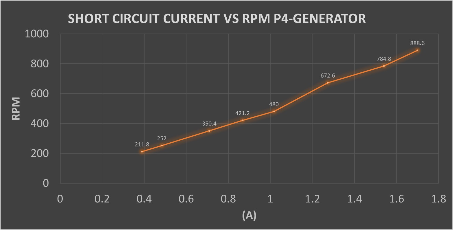
3- What is the maximum short circuit current at the expected RPM in the rotor?
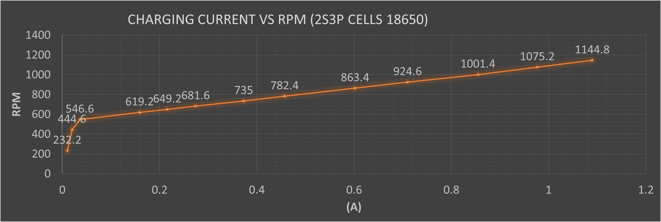
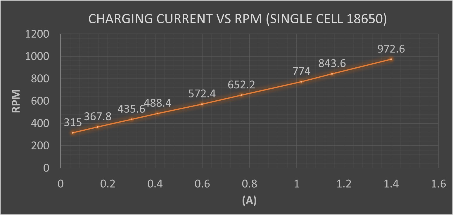
4- What is the best configuration of 18650 batteries (1S or 2S) for the storage of the energy generated in the wind turbine?
5- Does the use of DC-DC converters favor an increase in the charging current of the batteries with this generator and under the expected operating conditions?
The results presented below will influence the design of the Blades and the energy storage system.
The motor windings turned out to be approximately 6.5 Ohms. Recall that this generator was wound with 80 turns per pole in a star-shaped three-phase configuration. The wire gauge used was 0.35mm in diameter. In total there were 12 poles.
The motor turned out to be approximately 60kV, that is, for every 60 turns of the rotor, 1V is obtained. This graph shows the values obtained.
The maximum short circuit current was 1.7 (A) at 888 RPM. The results are shown below.
The charging current values in the single cell configuration are higher than those of 2 cells, however, the energy generated in both cases is very similar at the same RPM. I consider using the configuration of 2 18650 cells in series, since the resistance torque is less in the generator. It also makes it possible to obtain the necessary RPM for the rotor to work with good efficiency, at higher RPM. In addition, the resistance torque is less when the rotor begins to rotate.
The cells that were used are capable of storing 8.14Wh of Electric Energy each. In the case of the 2S3P battery, it has a total of 6 cells, which means that it is a 48.86Wh battery. If we divide this value by 7.4V, which is the nominal voltage value of two 18650 cells in series, we obtain that it is a 6600mAh battery. This Batt at a stable charge rate of 0.6 A would take around 11 hours (estimate) to fully charge. A Samsung Galaxy S22+ battery is 4500mAh, but at 3.7V, which translates to about 16.65Wh. Ignoring the energy losses, we can estimate that in 11 hours, you would be able to charge this phone at least approximately 3 times. About 3 hours and a half approximately for each charge of the phone.
There are several assumptions in this reasoning, but I think it gives an idea. Results may vary and charging current may be higher or lower on average, depending on wind speed.
A DC-DC (Boost-Buck) converter was also used in the experiments. At approximately 300 RPM in the generator, which corresponds to about 5V of voltage obtained, the converter begins to deliver an output at stable voltage. Through two potentiometers this value can be configured up to 35V. It is also possible to set the maximum delivery current of this module up to a maximum of 4A.
However, when the batteries to be charged are connected in both configurations (1S and 2S), it is not capable of regulating the output voltage. The voltage drops to similar values as if this converter were not connected. It seems that a much higher generation power is required to guarantee that this happens. It was concluded that it is better not to use it because there is no benefit in doing so, on the contrary, the efficiency decreases with its use.
Taking into consideration the previous conclusions, in the following Log I will present the new Blade designed for Prototype 4 as well as the chosen storage system.
Some Pics and a video of this process!


Thanks for following me here.
See you!
 adriancubas
Discussions
Become a Hackaday.io Member
Create an account to leave a comment. Already have an account? Log In.