-
Prototype 3!
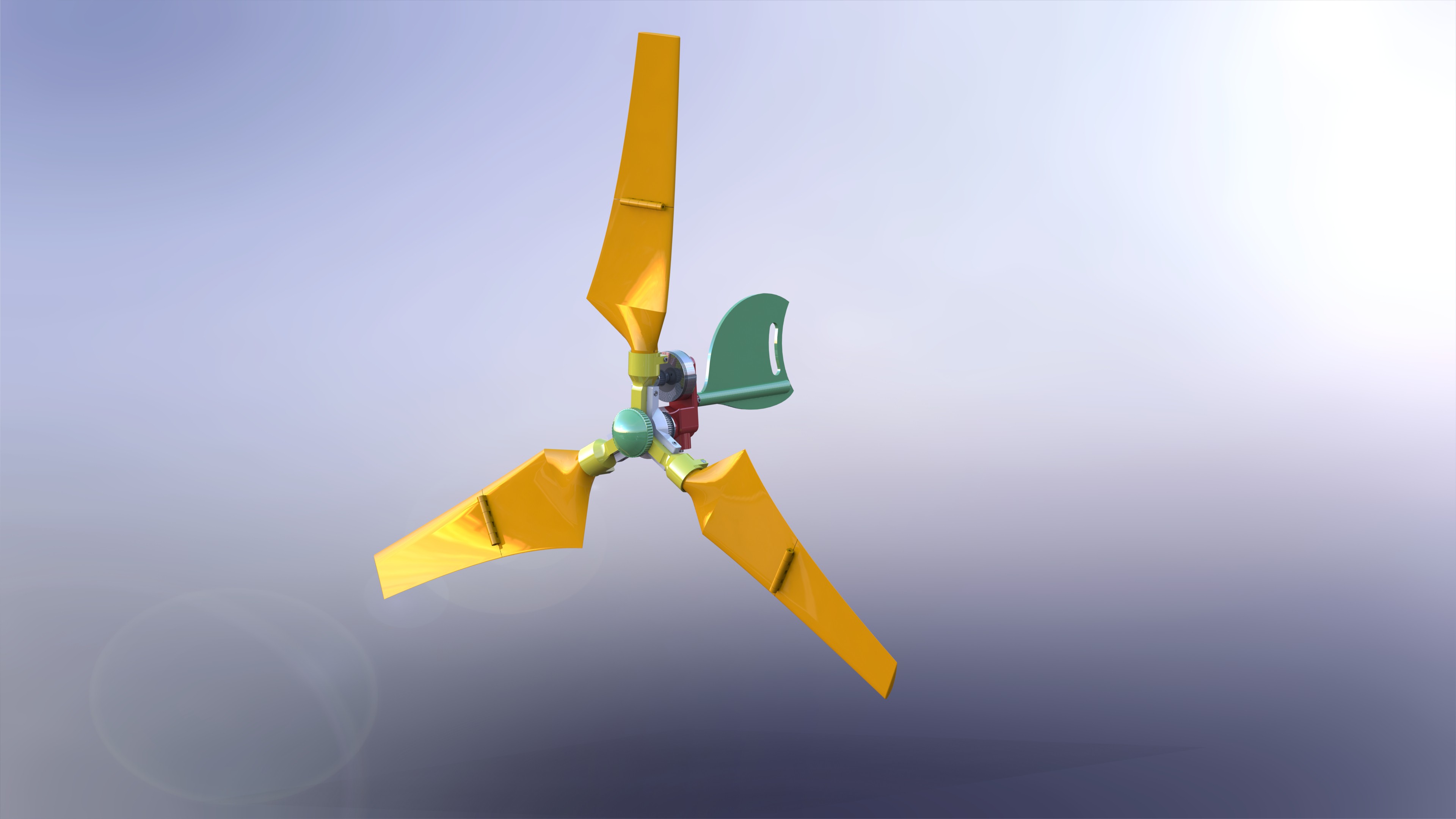
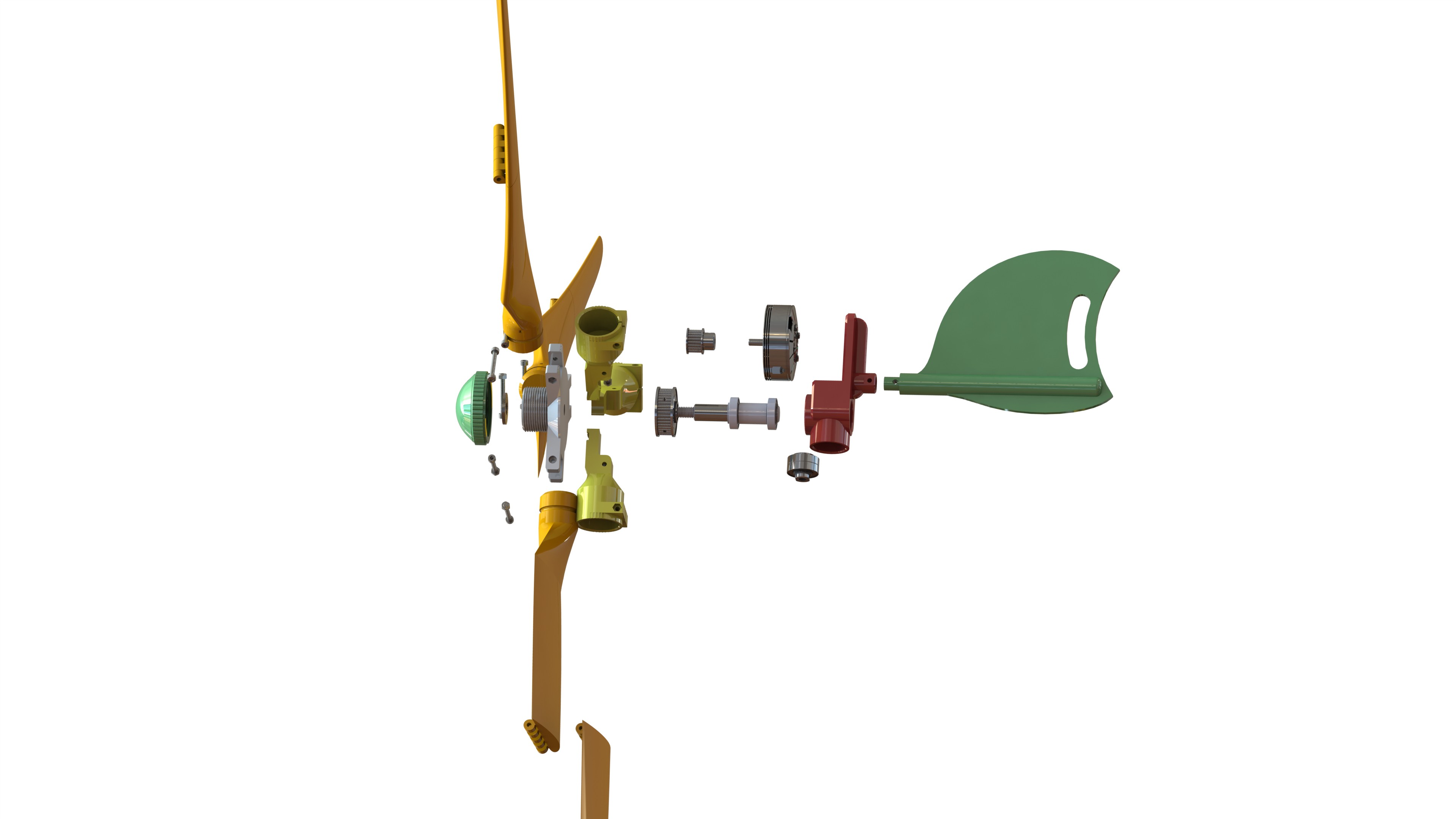
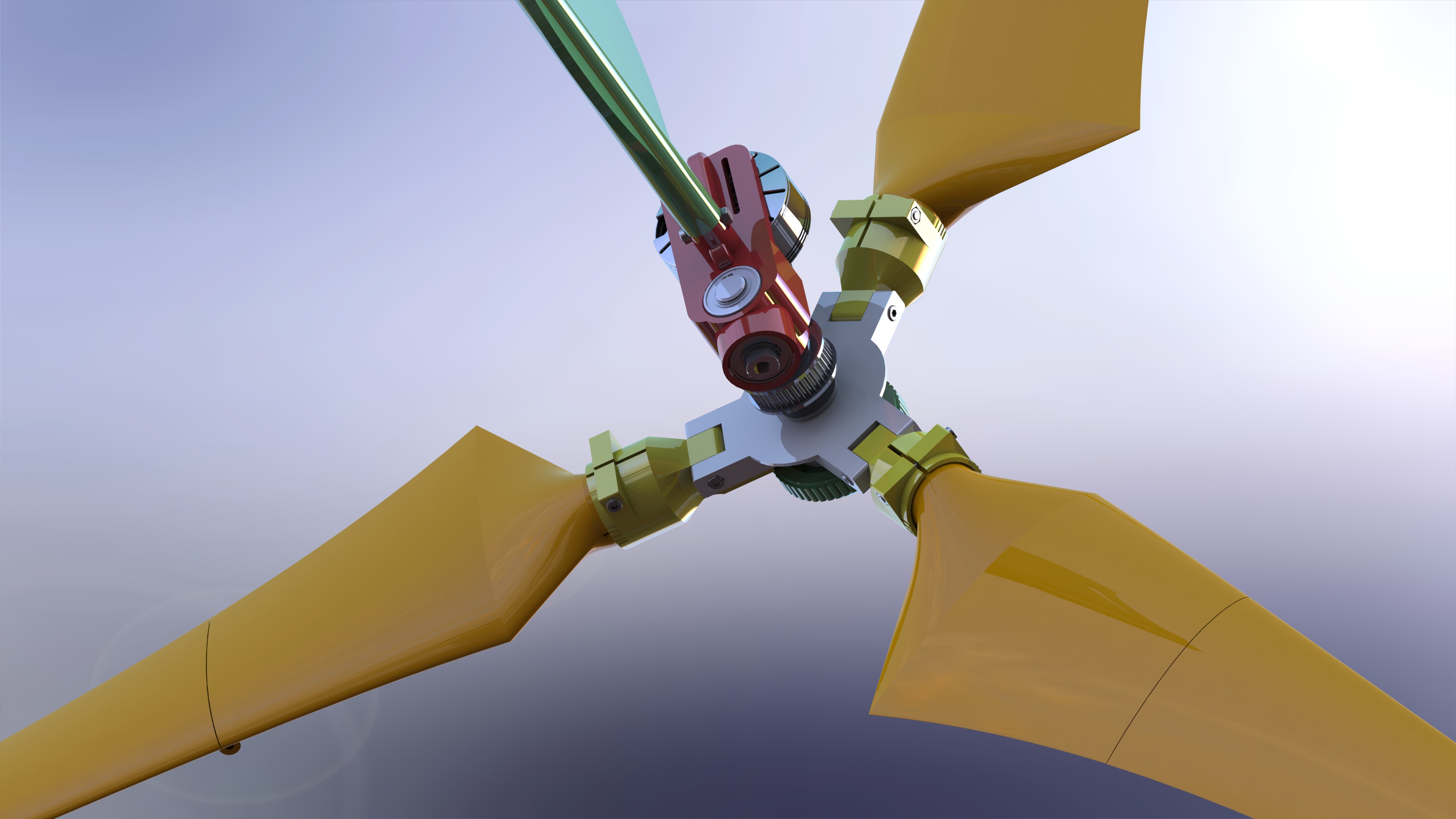
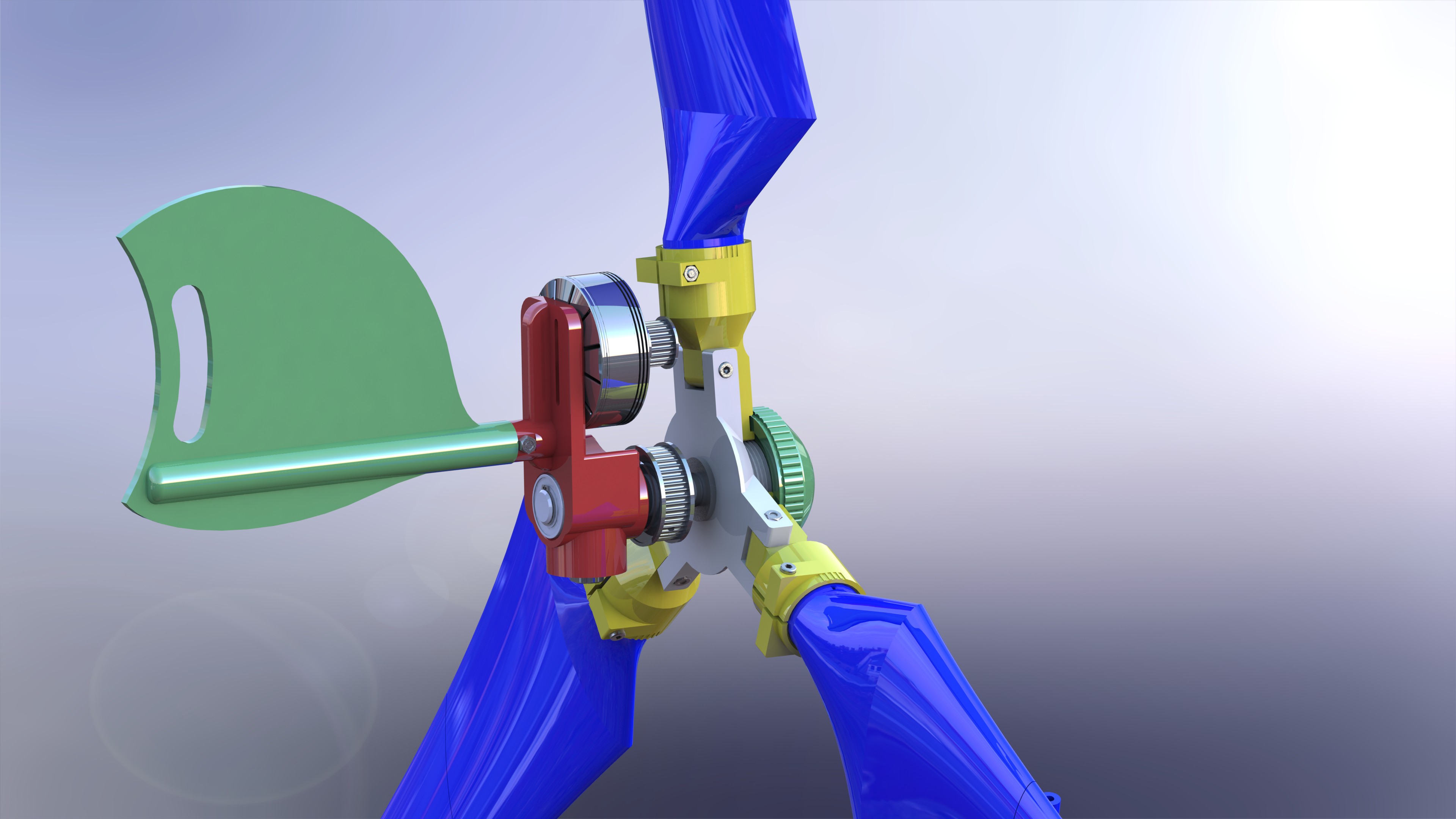
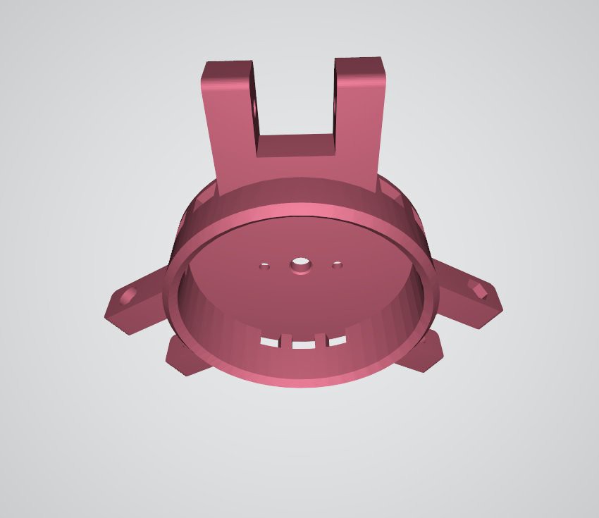
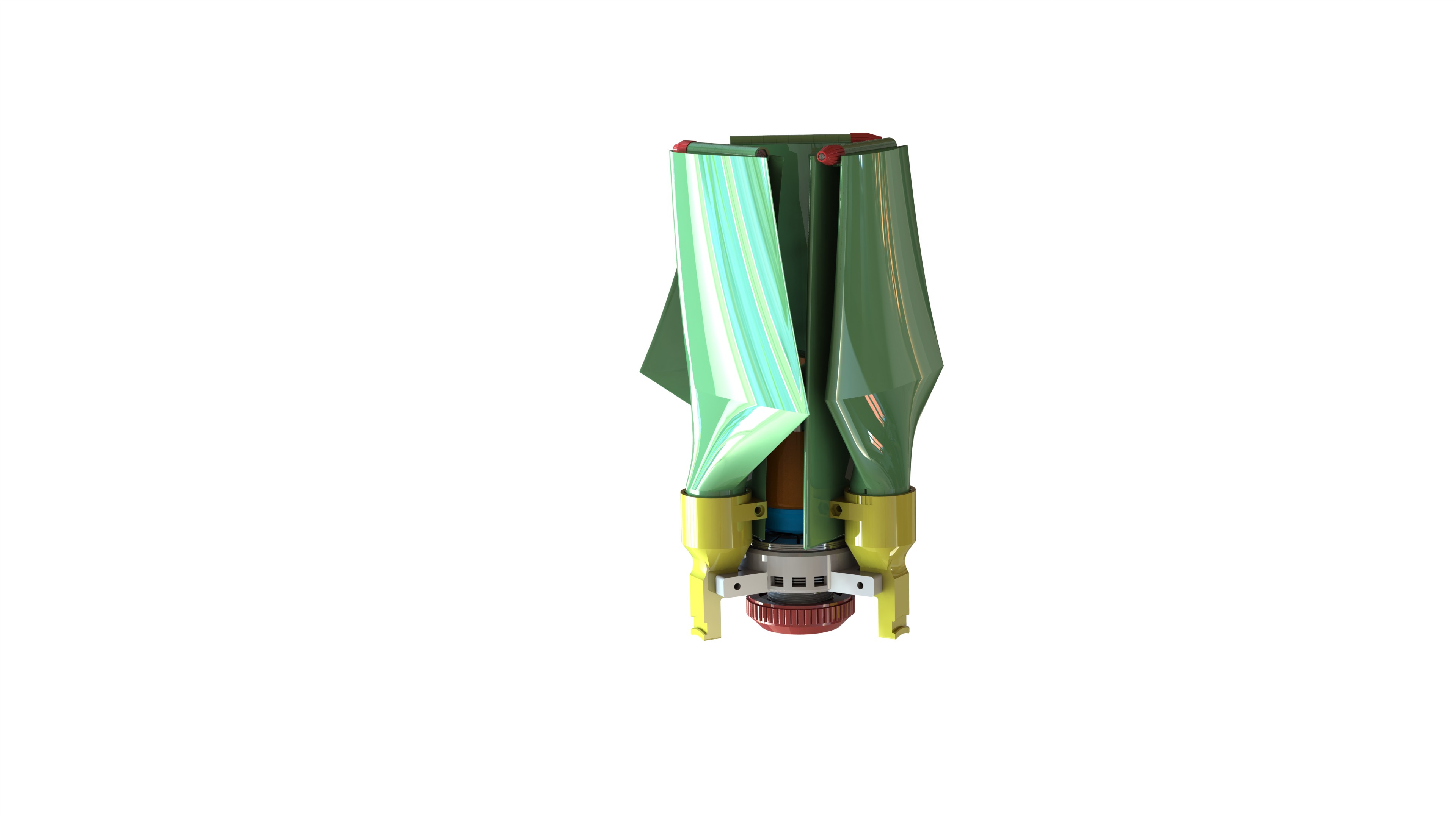
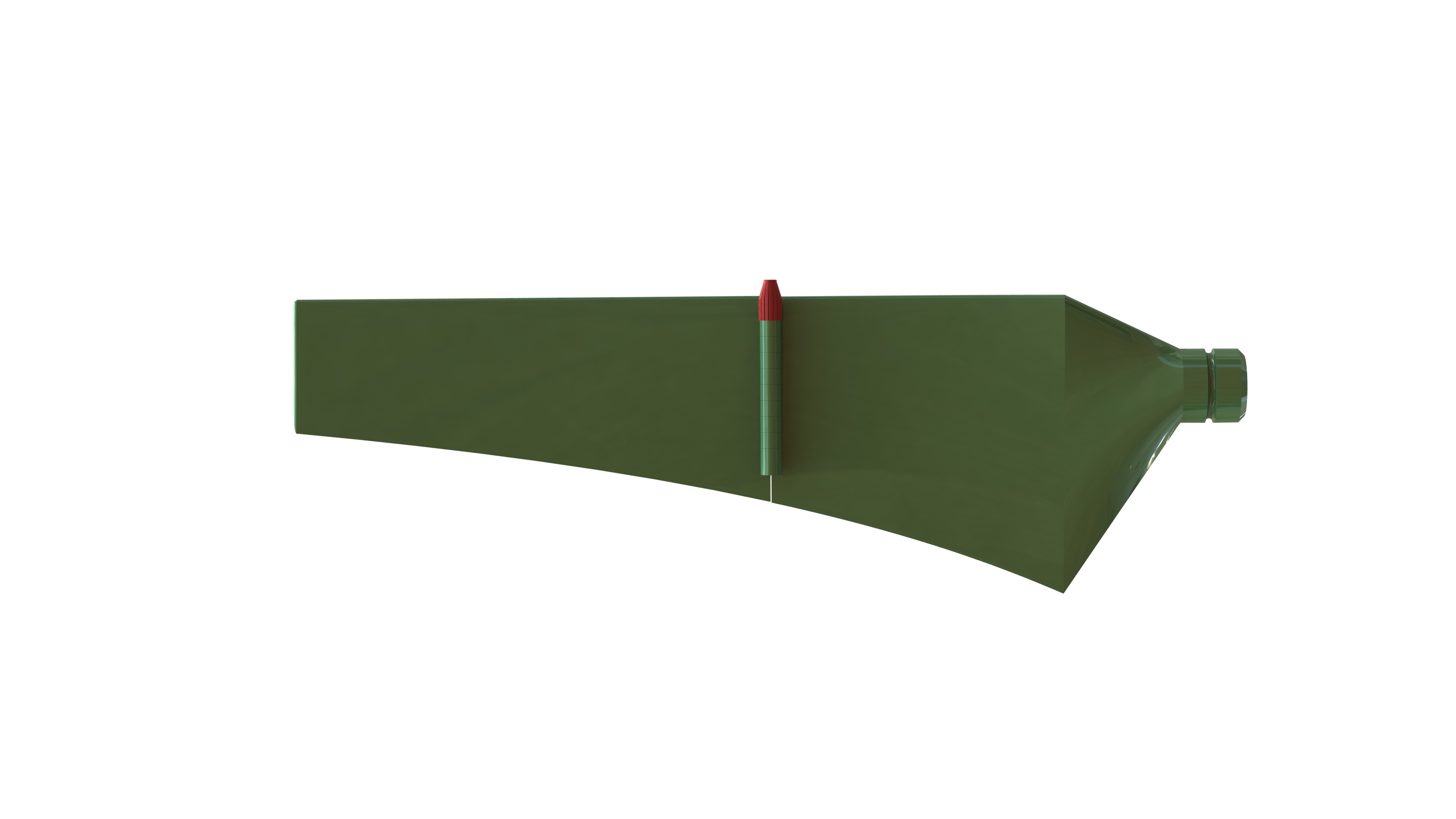
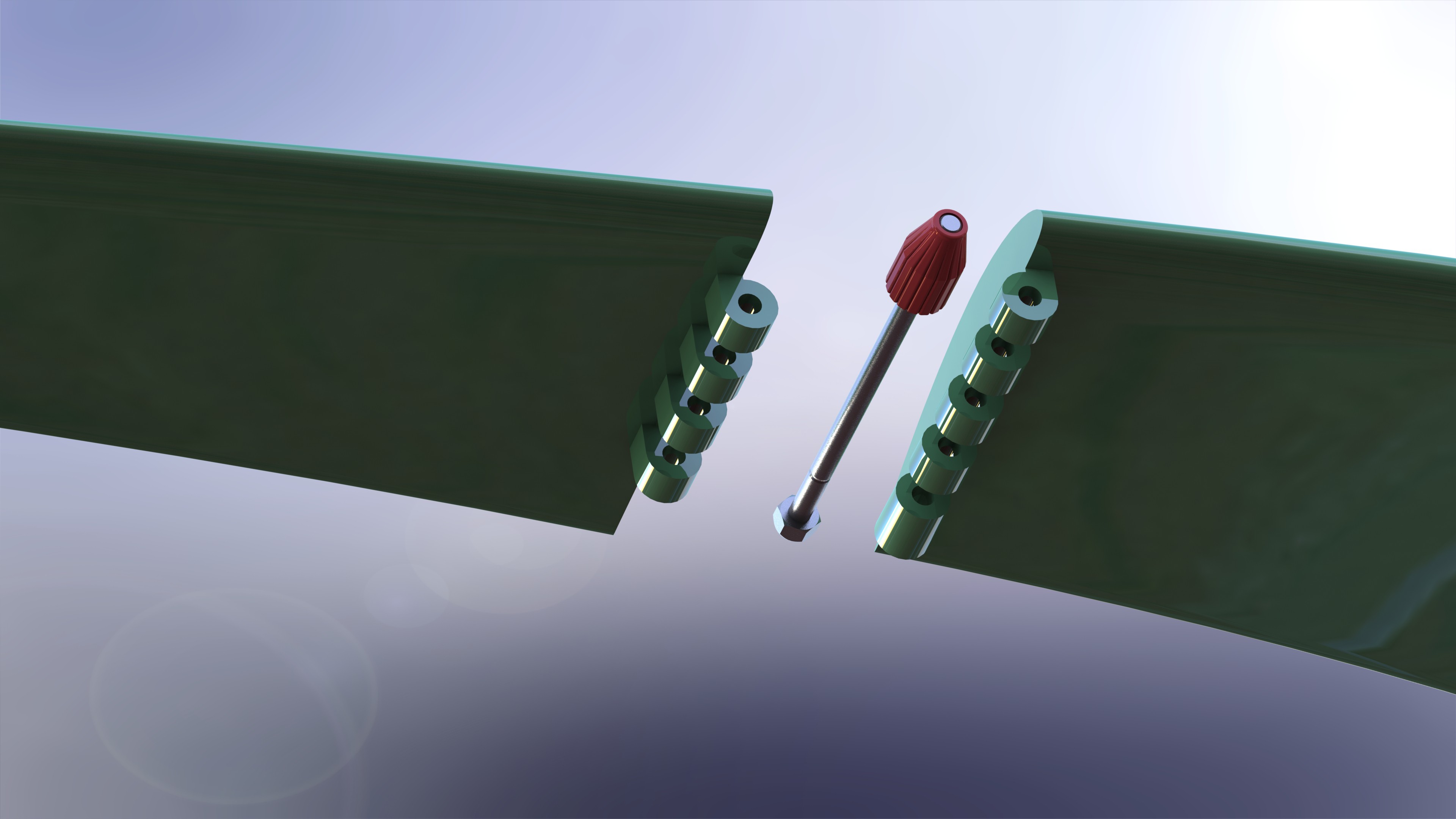
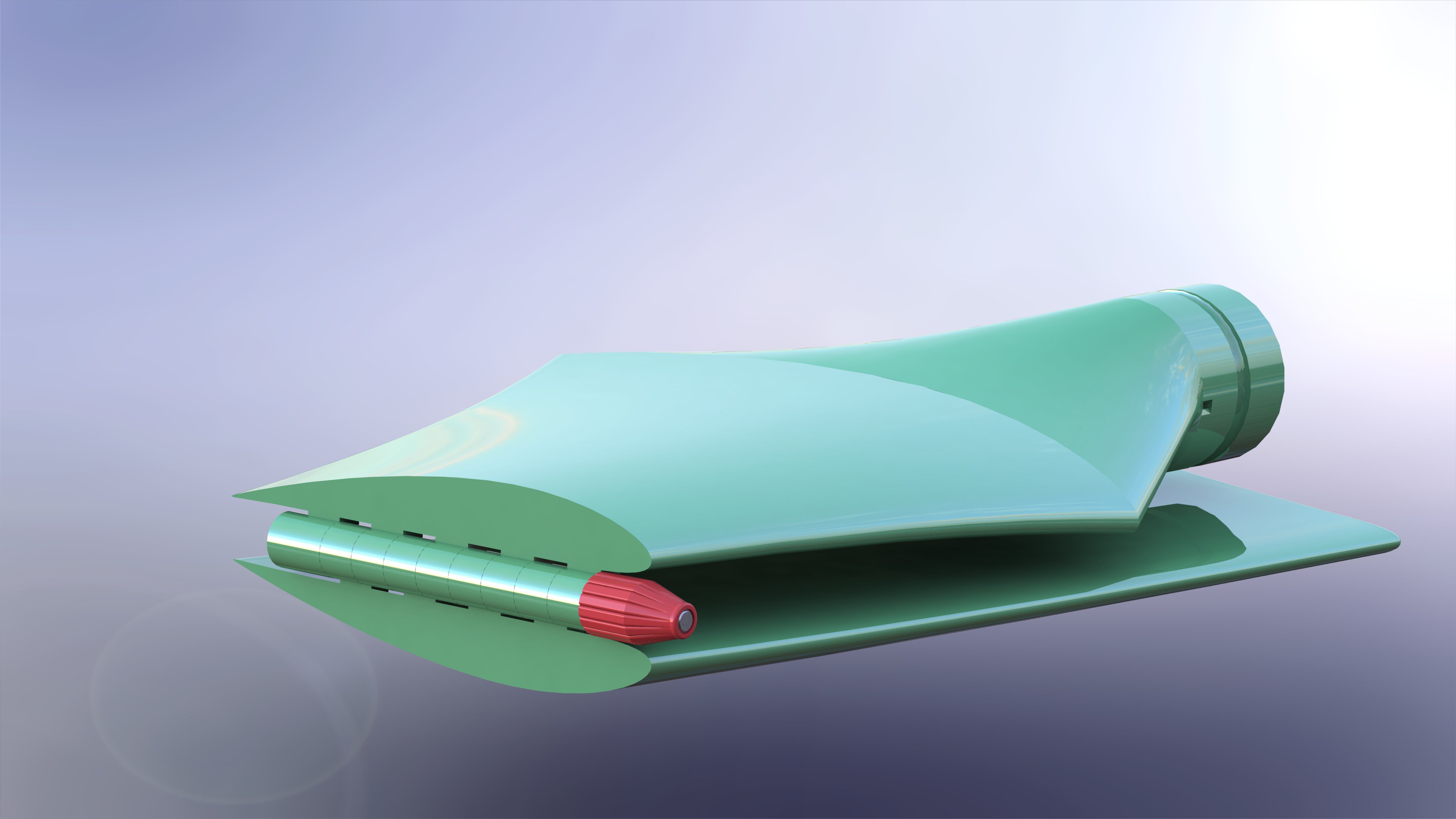
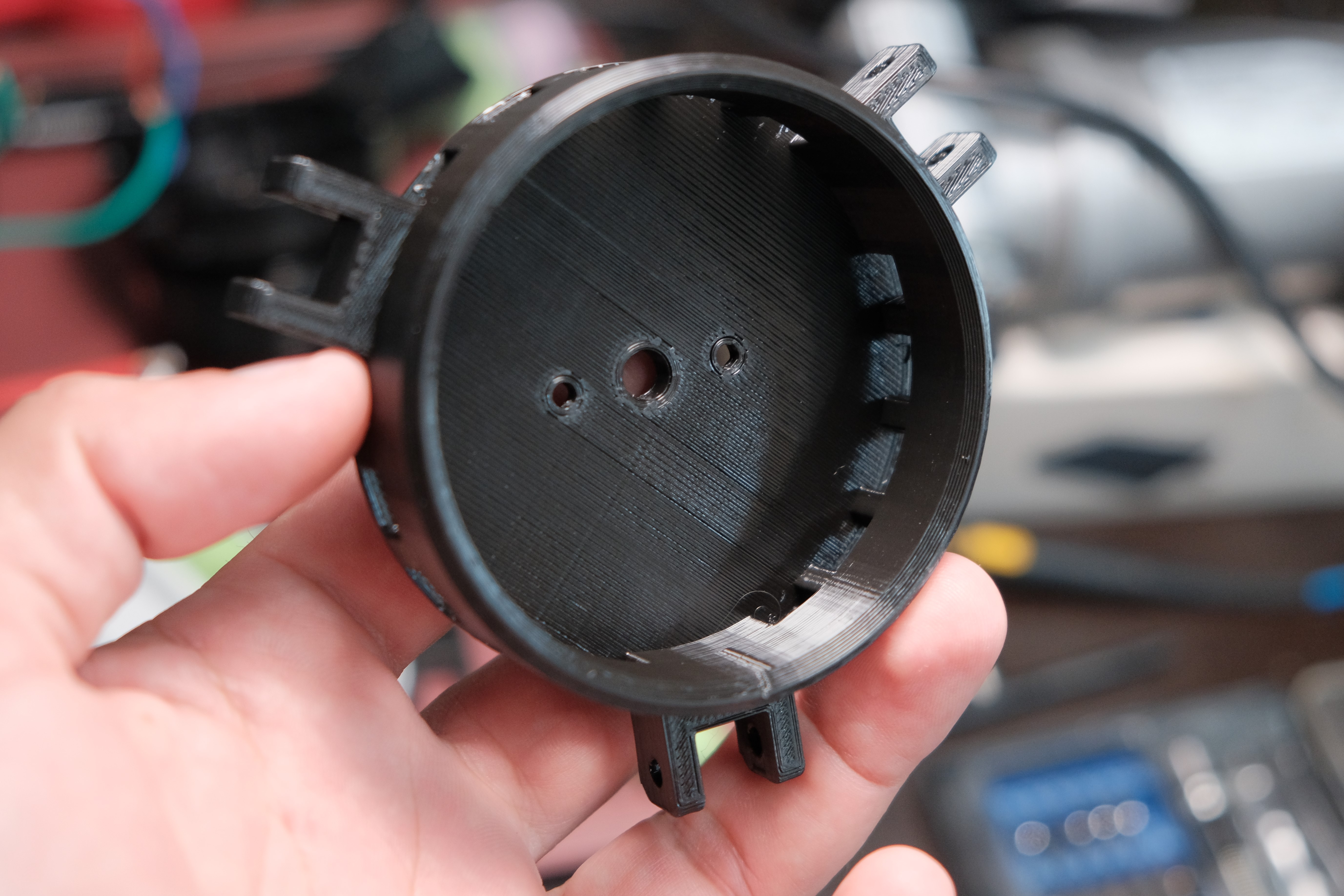
07/05/2022 at 17:24 • 0 commentsI have finished the mechanical design of prototype 3 and I think the final product should be very close to this design. Last changes can always arise, hopefully not many because it can be overwhelming. In this latest design, as you will notice, timing belts and pulleys have been used. I have used a 1:2 ratio but you can substitute it to a 1:3 ratio depending on the field tests. This time I do not plan to include any electronics in the body of the wind turbine, just a 3-pin connector for the three phases . Then I will design a box with the electronics and everything else.
I went back to the original idea that it was an upwind and not a downwind wind turbine. This design offers the possibility of using other motors (generators) with some small changes in the central body part.
I will publish in the gallery some renders that I have done. That's all, see you in a next Log! -
Backyard's first tests of prototype 2
06/29/2022 at 01:12 • 3 comments
I needed to do these tests because I have to decide if I need to use gears or other power transmission mechanisms, in which case I would change the design a bit.It is not enough to make the propellers rotate, it is necessary to generate an adequate voltage and current value for storage in batteries and subsequent use, hence the need for these mechanisms may arise.
We should remember that I already tried to rewind BLDC motors to get higher voltages. The ferromagnetic cores of the stator have limited space for the copper wire and to increase the number of turns per pole it is necessary to use finer gauge wires which greatly limits the output power. Since this Wind Turbine has to be small because it is "portable" I find this solution unfeasible for the power I want with this new prototype. If the power is not something of primary interest, then I recommend building the Prototype 1 which is much simpler than this and guarantees about 3-6W of Power without major complications.
During the first phase of the tests I verified that the propellers could rotate and start the movement by themselves without gears. In this case, the motor is directly coupled to the hub as it was assembled in the previous Log. Unfortunately there was no wind at all that day and I had to use a common household fan. You may not see it in the video, but the fan blades are much shorter than the wind generator blades. This constitutes a limitation, but in spite of it it began to rotate. From my previous experiments I have been able to learn that if it works with the turbulent and relatively low flow that a fan provides it will do very well in real world conditions. Luckily nothing came off or flew away hahaha!!! The maximum voltage obtained was 2.66V, a bit low for my needs. This voltage value corresponds to about 400 RPM according to my previous experimental results. I know that this voltage value could be increased in suitable wind conditions. My intention is to manage to charge 18650 lithium cells connected in parallel until they reach their maximum voltage of 4.2V. The number of cells in parallel will depend on the generation current. BMS, Buck boost converters, Power Meter and others are required that when I finish this part of the Project I will have to integrate.
During the second Phase I did some tests on the generator, but this time coupled to gears with a 1:4 ratio. As can be seen, it is not capable of starting the movement on its own, although it is capable of sustaining it without problems once a minimum RPM has been reached. An automatic angle of attack variation system would perhaps be a benefit. A higher angle of attack would guarantee the start of the rotation and then the angle of attack would be decreased to achieve higher RPM and improve efficiency. This would make this project much more complex and would also make it more expensive, something that I prefer to avoid.
I think I am going to redesign the generator to integrate a 1:2 ratio power transmission system. I would like to know your opinion.
See you in a next Log!!!
-
Full bridge rectifier + capacitor circuit
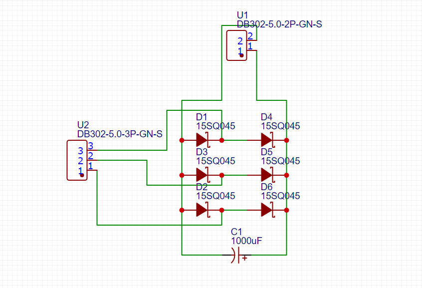
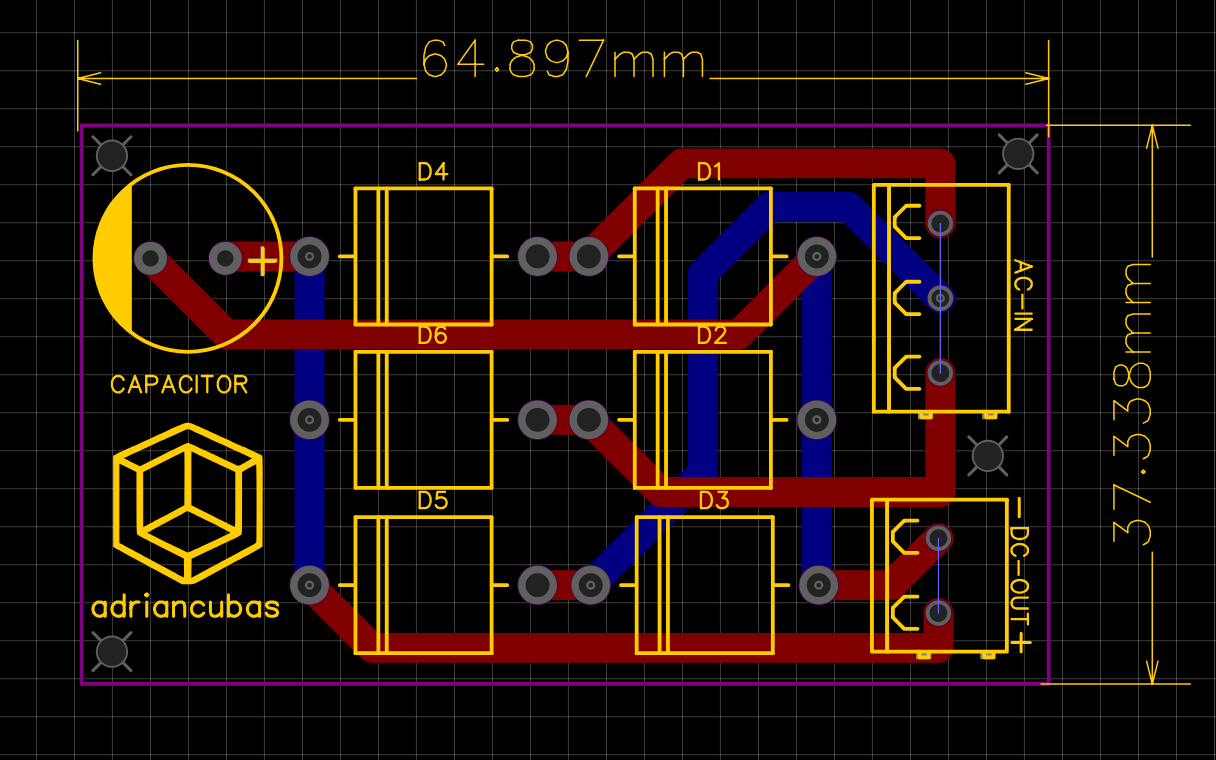
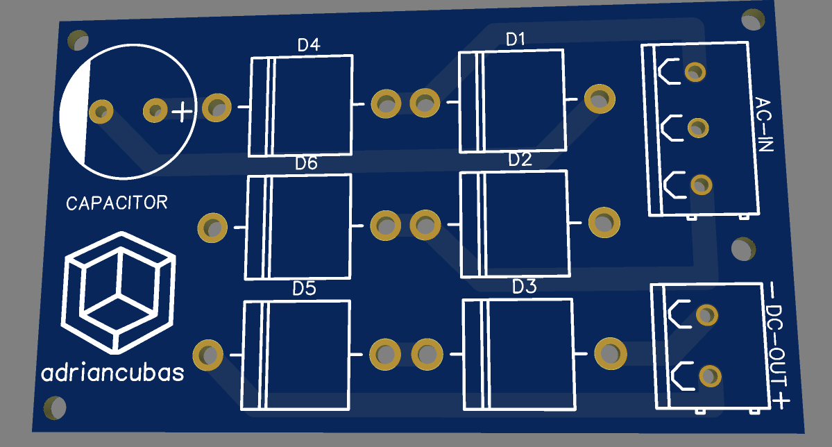
06/23/2022 at 14:26 • 0 commentsI have designed this rectifier circuit using Schottky diodes capable of withstanding 15 amps. Perhaps it is an exaggeration but I prefer to be prepared for any surprise. The use of these diodes guarantees lower losses in the rectification process compared to more common rectifier units.
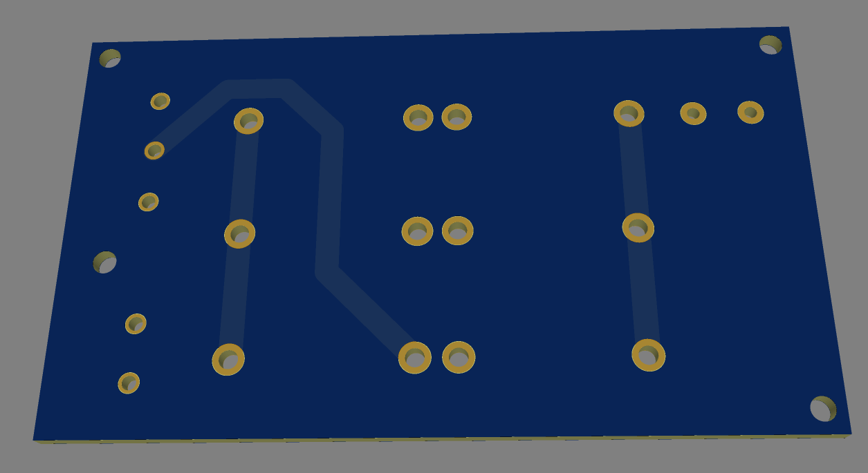
If you wish, you can now download the Gerbers Files and print the PCBs from the Files section.
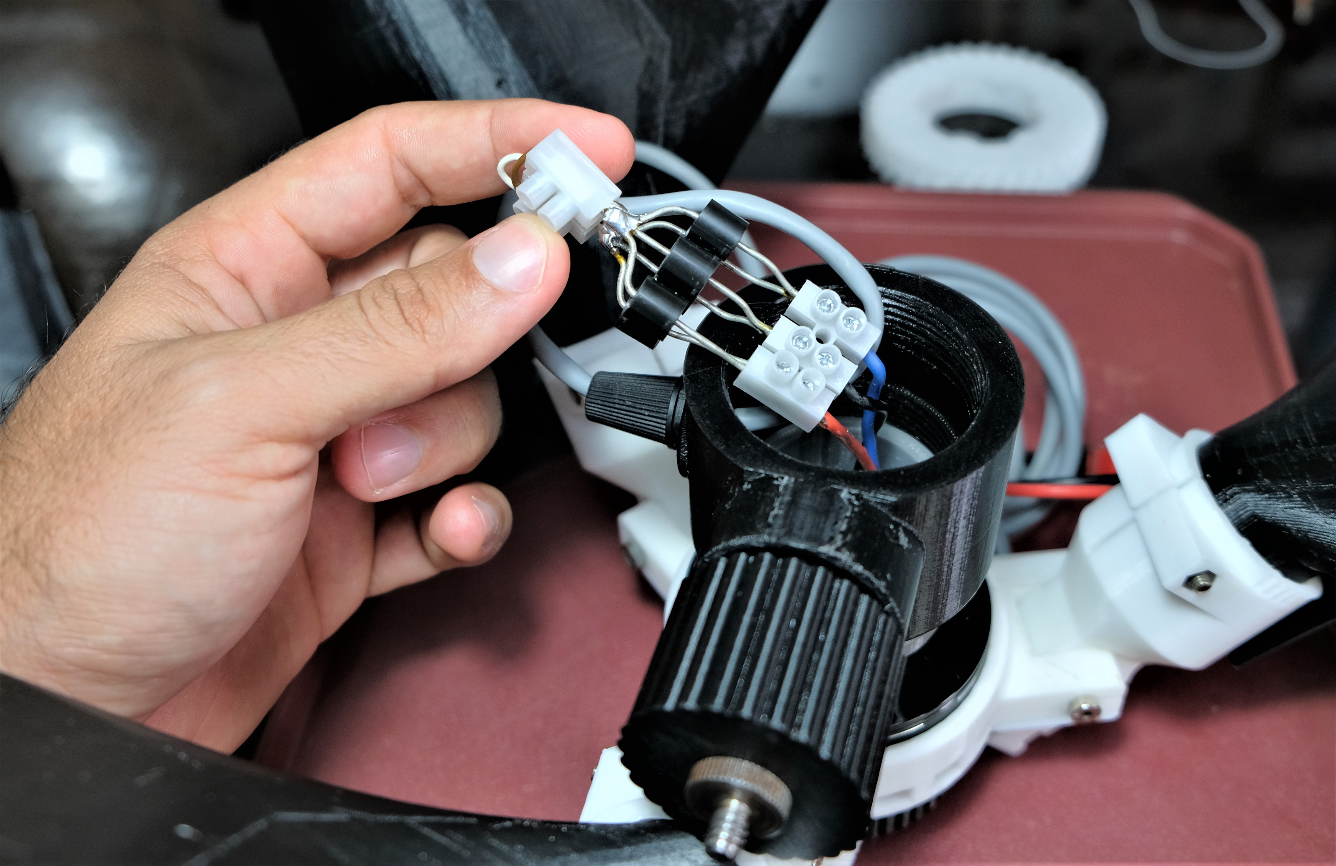
In my case I made the connections quickly with cable connectors as shown in the photo and it went very well.
Having completed this stage guarantees to make the measurements and experiments that I want to do perhaps in the next week. I plan of course to post here the process and its results.
See you in a next Log!![]()
![]()
![]()
![]()
-
From design to reality!
06/09/2022 at 01:46 • 0 commentsThis video shows the position and assembly of the fundamental pieces of the central body. In a future log I will show some electrical measurements, before going into the design of the electronic rectification and regulation circuits.
-
The Mechanical Design of Prototype 2 is almost complete!
06/01/2022 at 19:28 • 0 commentsI have been working hard to finish the mechanical design of this new variant of Portable Wind Turbine. As you can see in the image some changes have been made. It is now a Down-Wind Wind Turbine. A new blade grip system has been designed that allows you to manually change the angle of attack of the blade and experiment without having to glue it down. Although folded it is of similar dimensions to prototype 1, its power is much higher. Blades are almost twice as long.
As I have designed the pieces I try to print them and physically test them with the rest of the assembly, if everything goes well I continue the other parts of the design. Printing them is taking me a long time since I have printed them at 100 percent infill except for the Blades
I am impatient to test this new model.
Cheers!![]()
![]()
![]()
![]()
![]()
![]()
-
SPLIT BLADE 2 ?
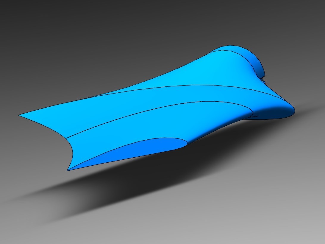
05/27/2022 at 23:39 • 0 commentsI have sacrificed a bit of the efficiency of the Blade2 for more portability. If it didn't, the Wind Turbine became very high. These are the results of the SPLIT-BLADE2 modeling.
-
BLADE 2 is Here!
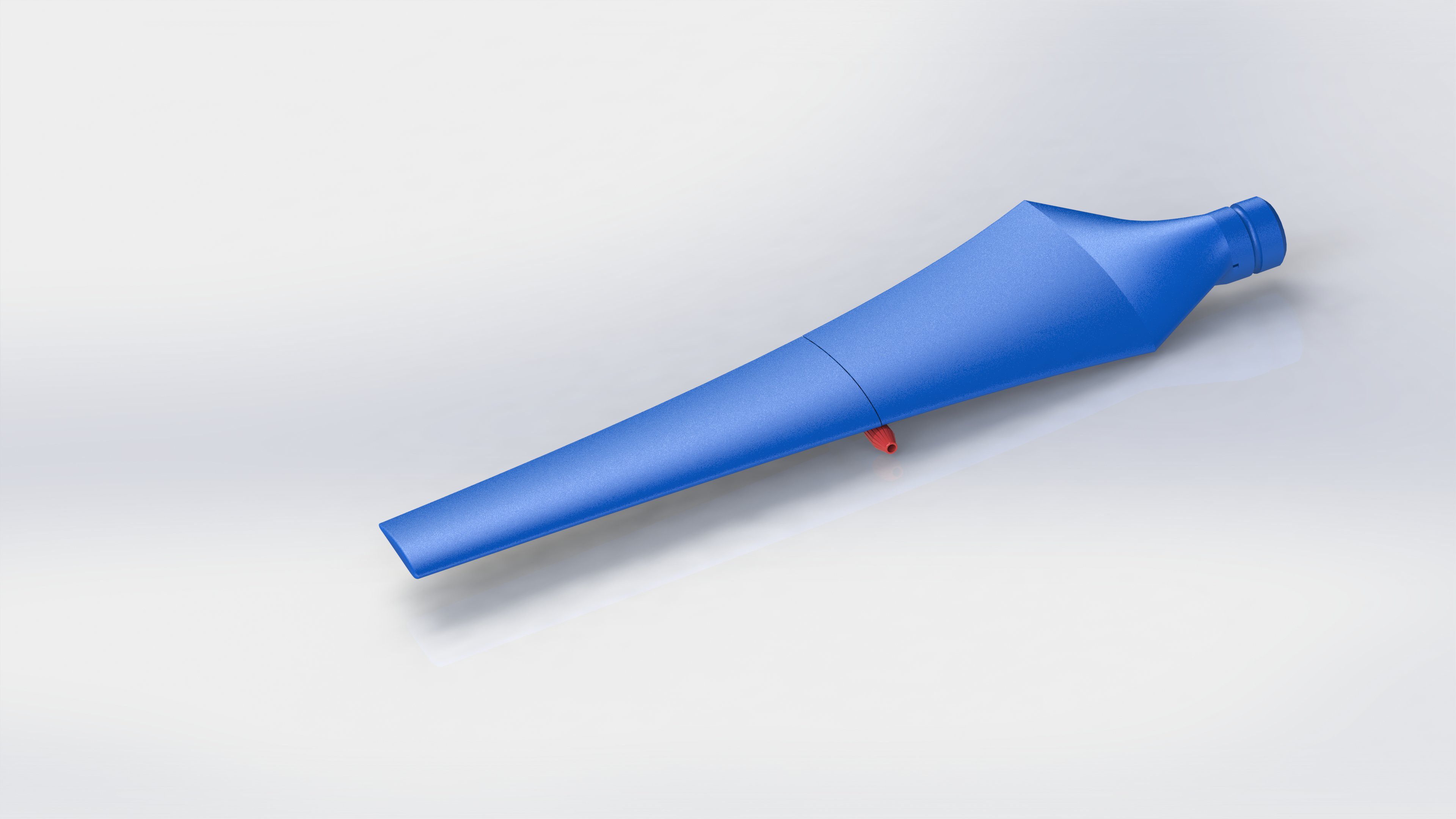
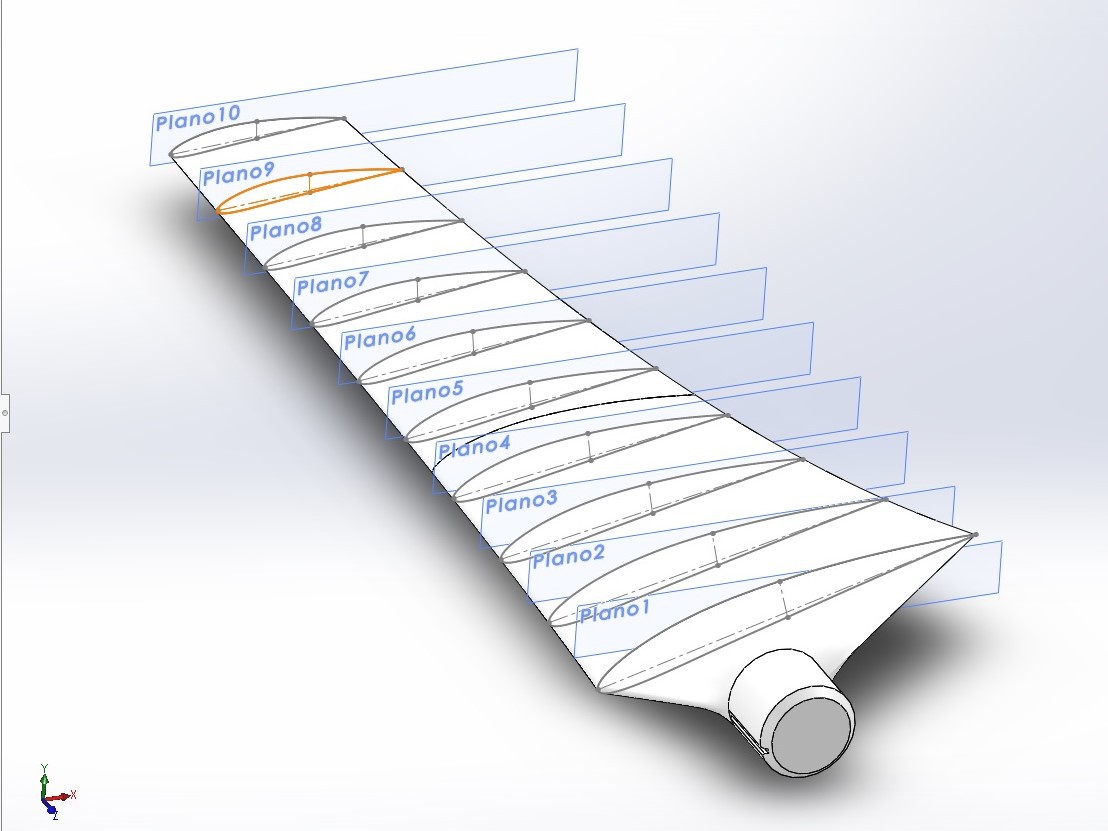
05/25/2022 at 16:47 • 0 commentsI have finished the design of the new Blade that I want to use in prototype 2.
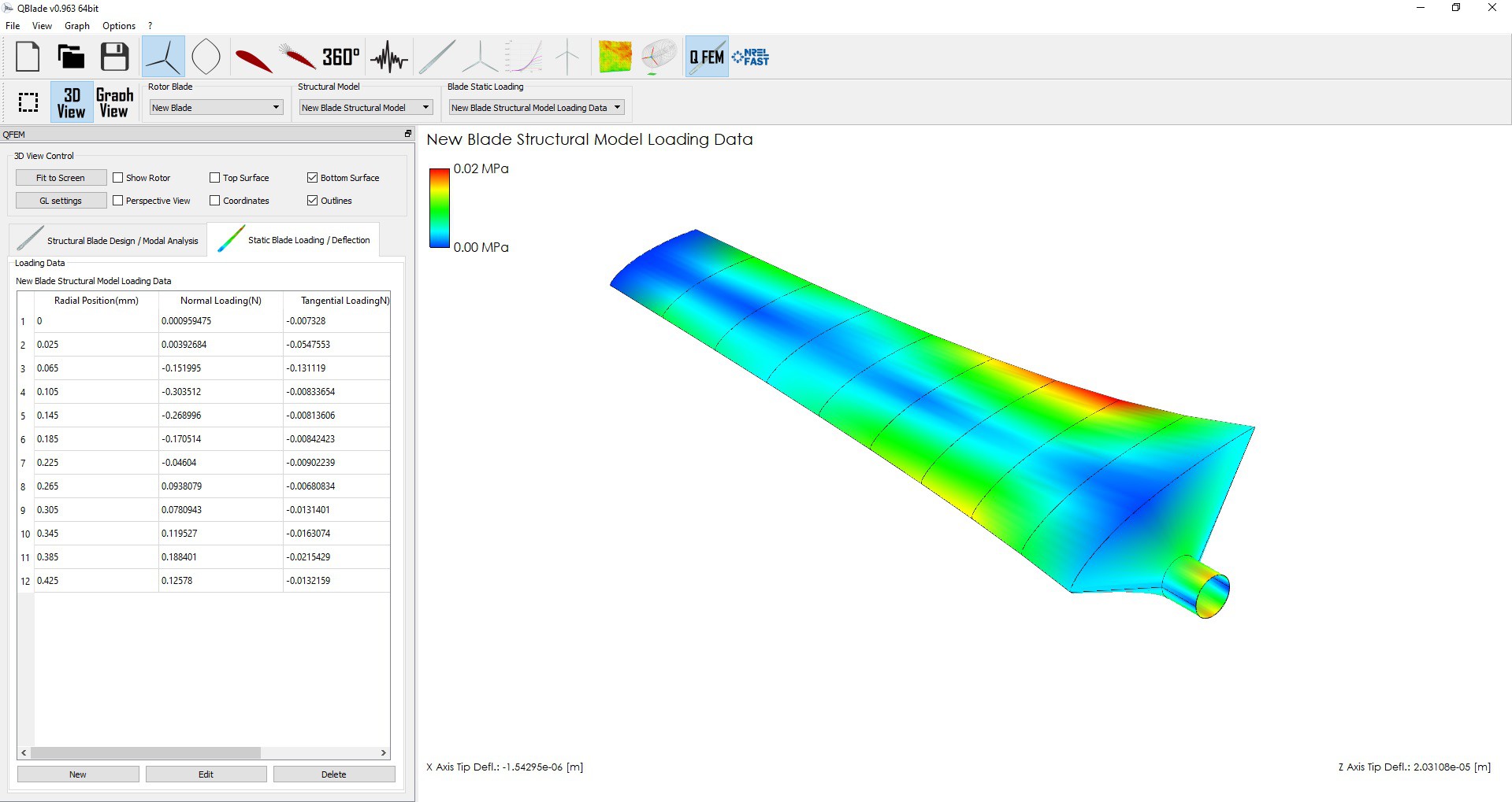
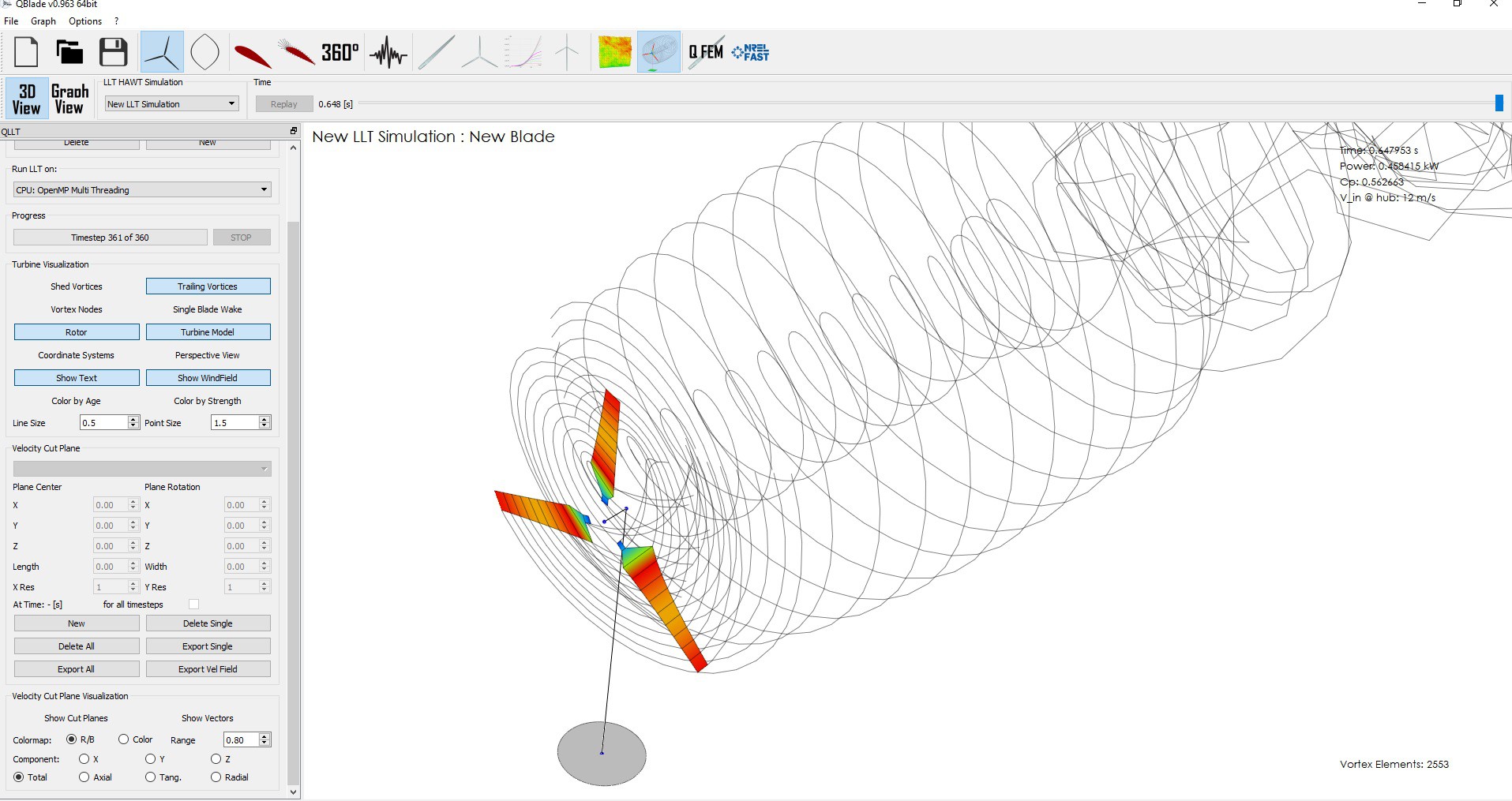
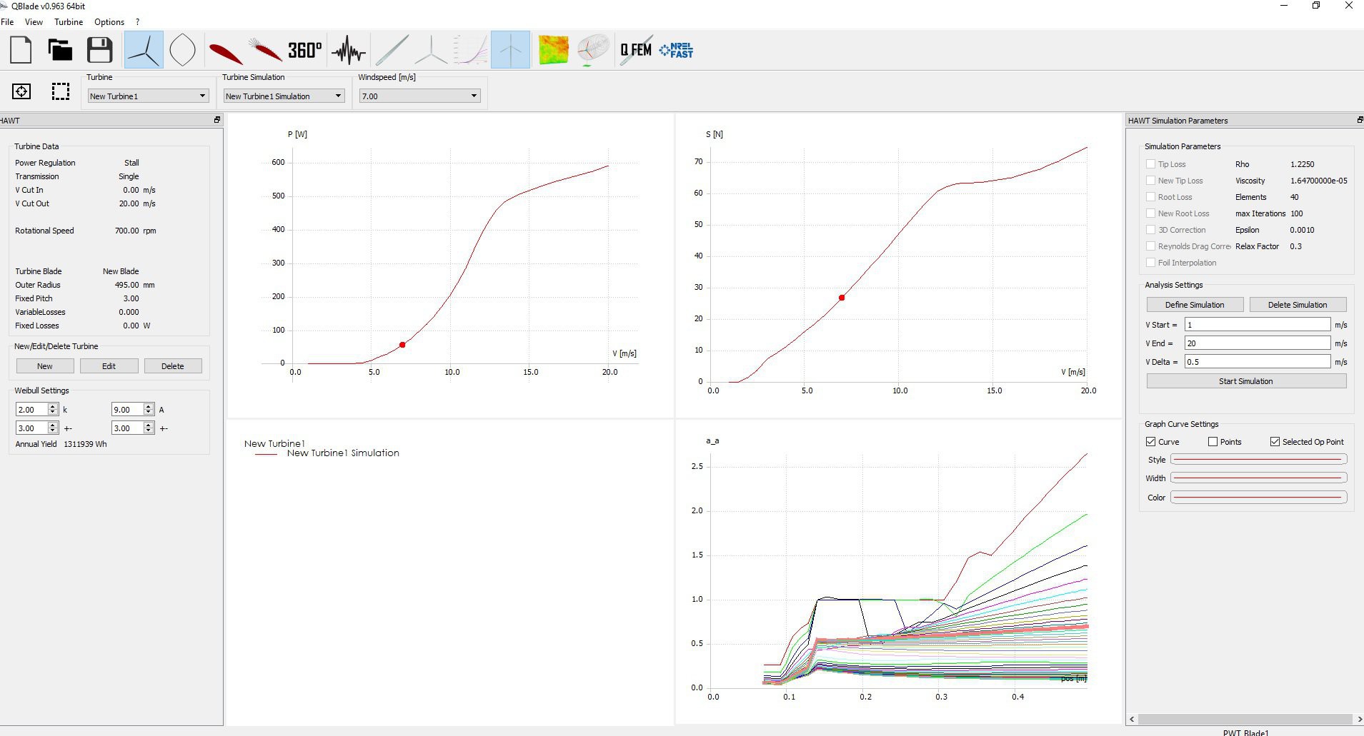
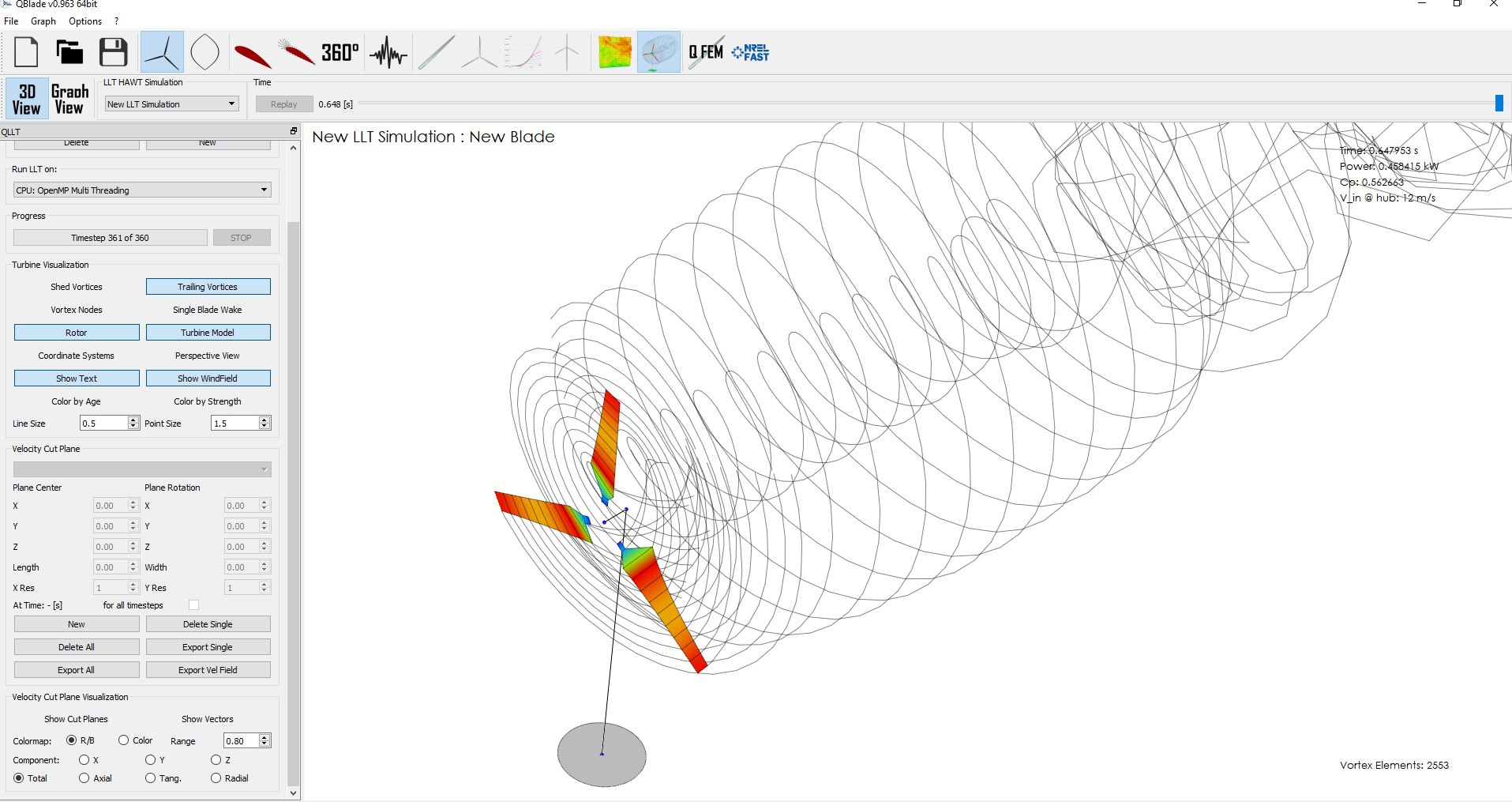
The geometry I got from the QBLADE 0.96 Software which you can download and use for free. I've attached the design and simulation file for my new Blade if you'd like to take a look. I would appreciate any suggestion.
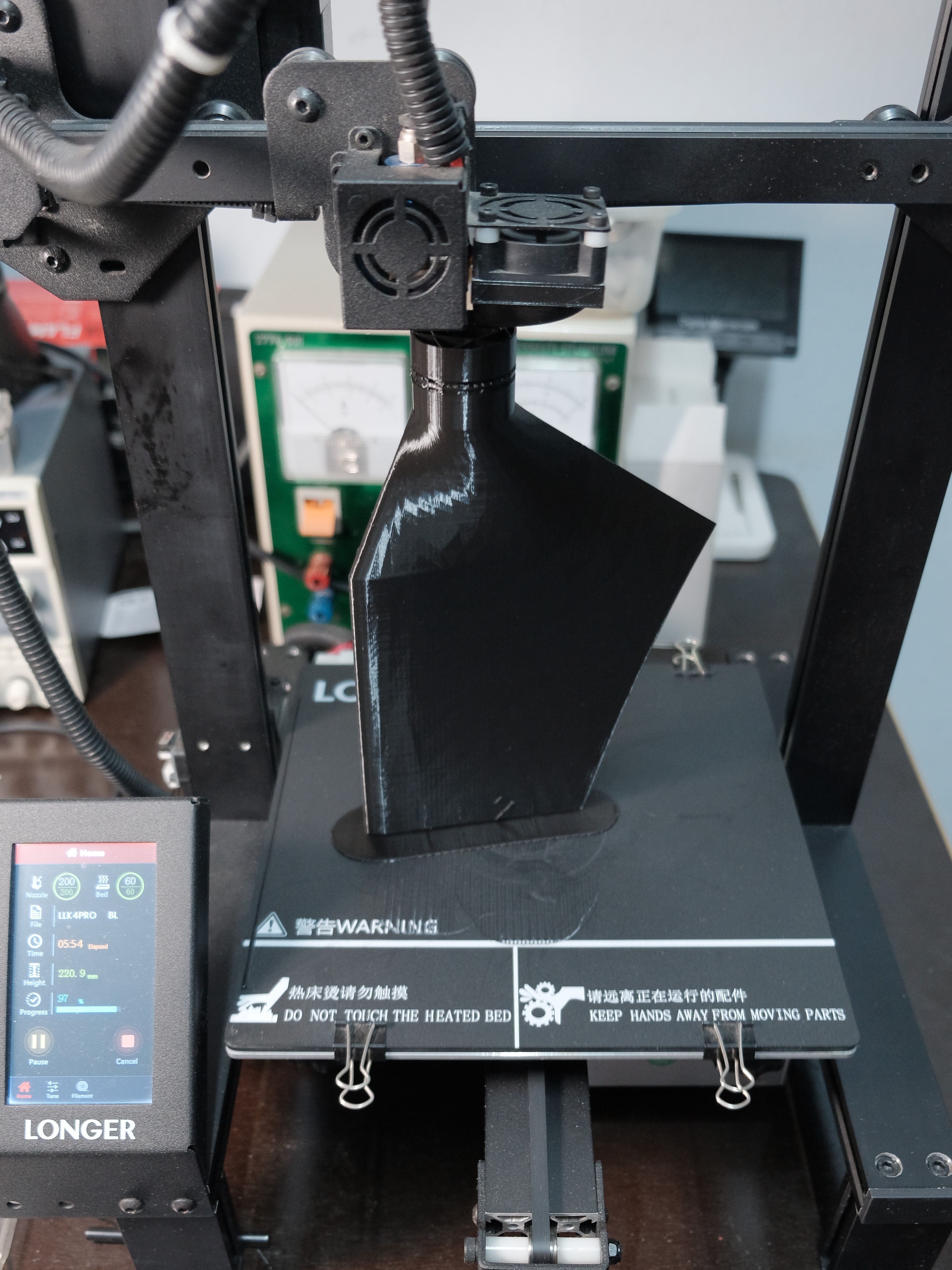
In order to obtain the power values that I want in this new prototype and to make its performance consistent with those obtained in the BLDC generator that I presented in the previous log, I had to increase the length of the Blade Prototype 2 to approximately 435mm. Since the 3D printer I have is unable to print objects of that height, I have sectioned the Blade into two parts which must be assembled later with epoxy glue and inserts.Kyle ( https://hackaday.io/ky6Brav0 ) works for Essentium Inc (https://www.essentium.com ), an industrial grade 3D printer / materials company based in Austin, Texas and has been kind enough to print some parts of prototype 1 in the following materials:
https://www.essentium.com/product/essentium-pet-cf/
https://www.essentium.com/product/essentium-9085/
https://www.essentium.com/product/essentium-htn/
He just sent them to me. The use of these materials, with exceptional properties, guarantee an incredible durability and resistance of this Wind Turbine.
![]()
![]()
![]()
![]()
![]()
-
FROM STEPPER MOTOR TO BLDC GENERATOR
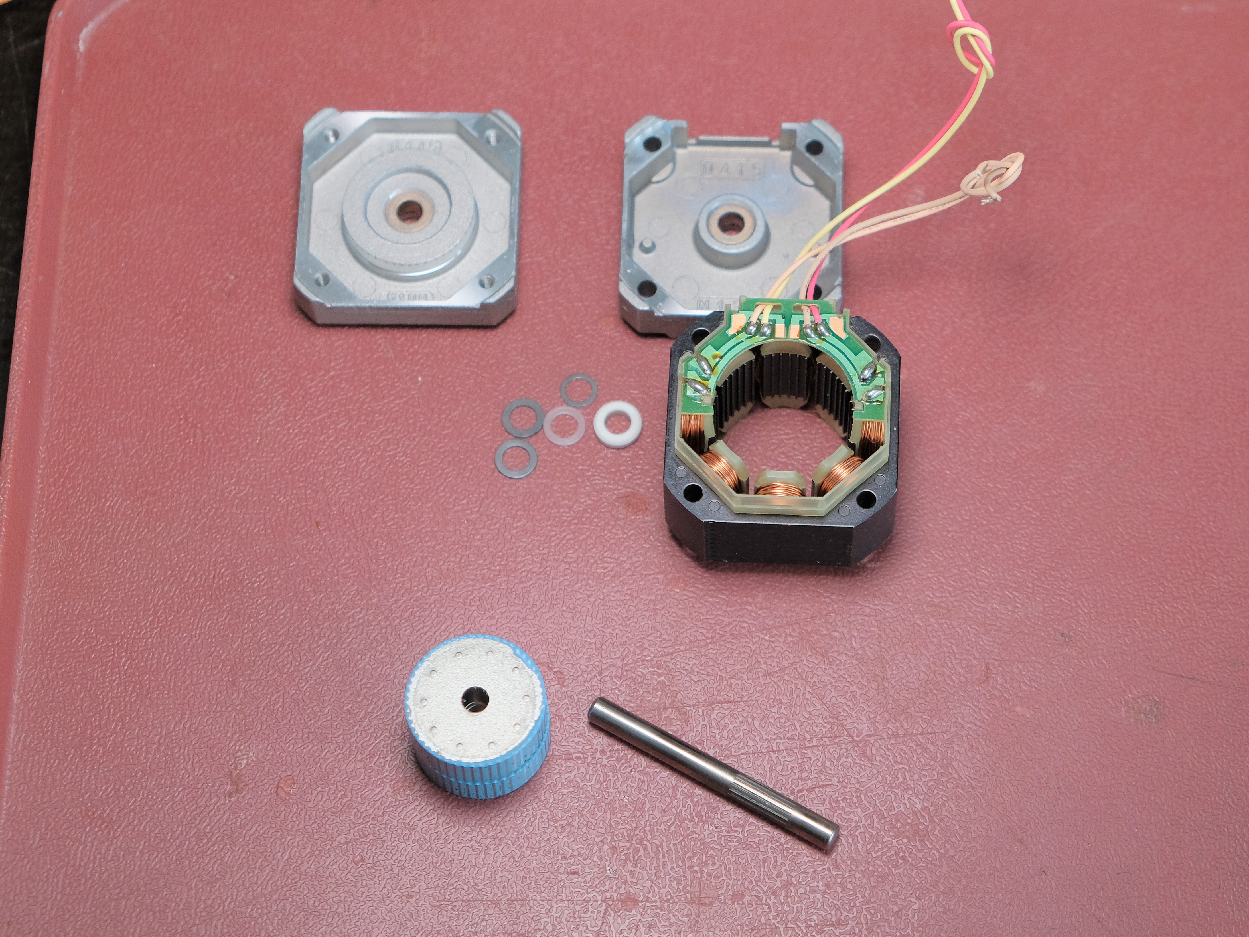
05/20/2022 at 18:30 • 0 commentsI have been experimenting with different motors (generators) in order to increase the generating power of the wind turbine. As I presented earlier during my measurements, the nema 17 stepper motor is only capable of delivering 0.65A of maximum short-circuit current even though the RPM is notably increased. I know I can get more than that.
My first intention was to design a new permanent magnet rotor for the stepper motor and I did so but the results I got were still poor, plus it required modifying the stepper which could be challenging.
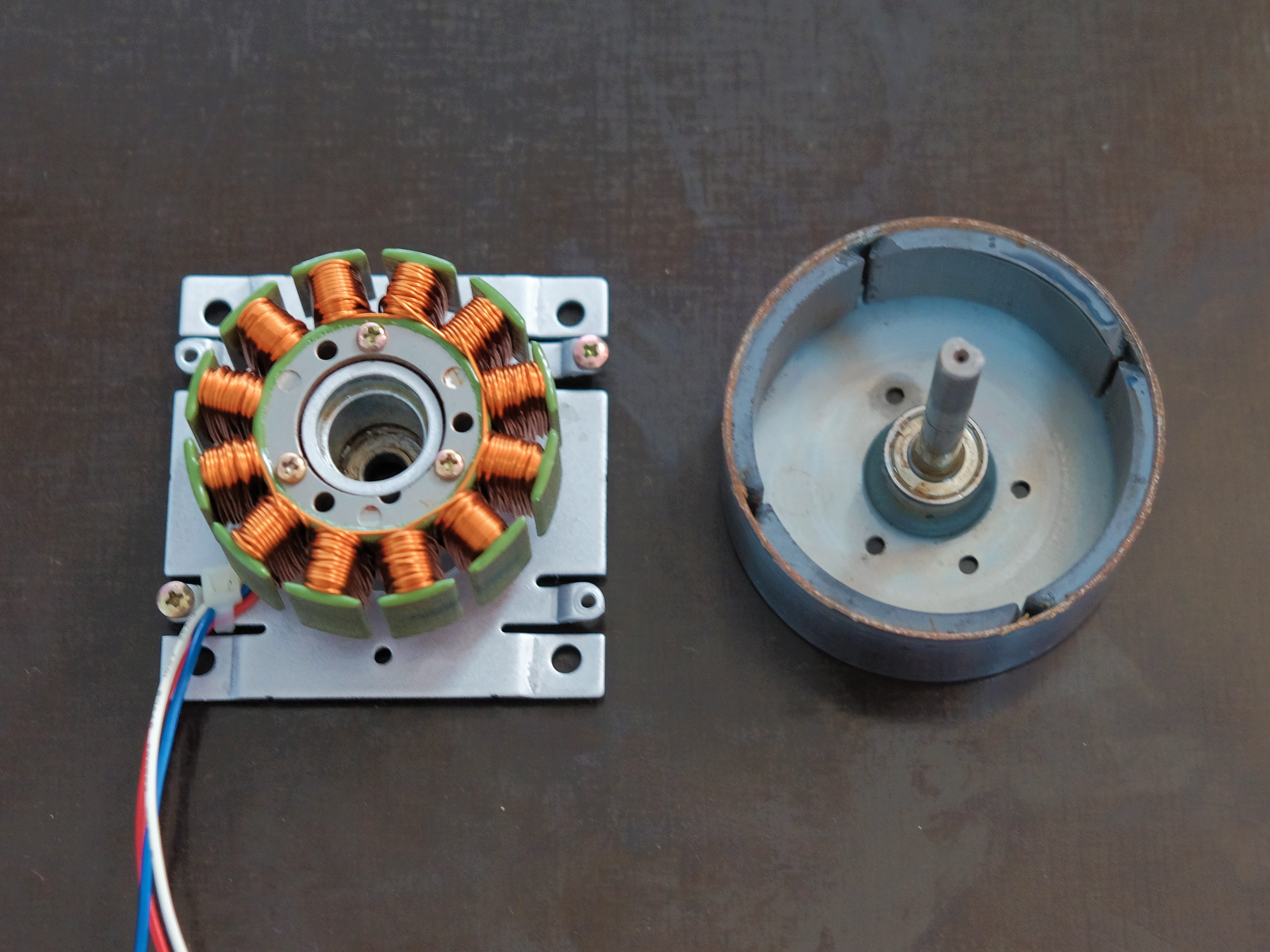
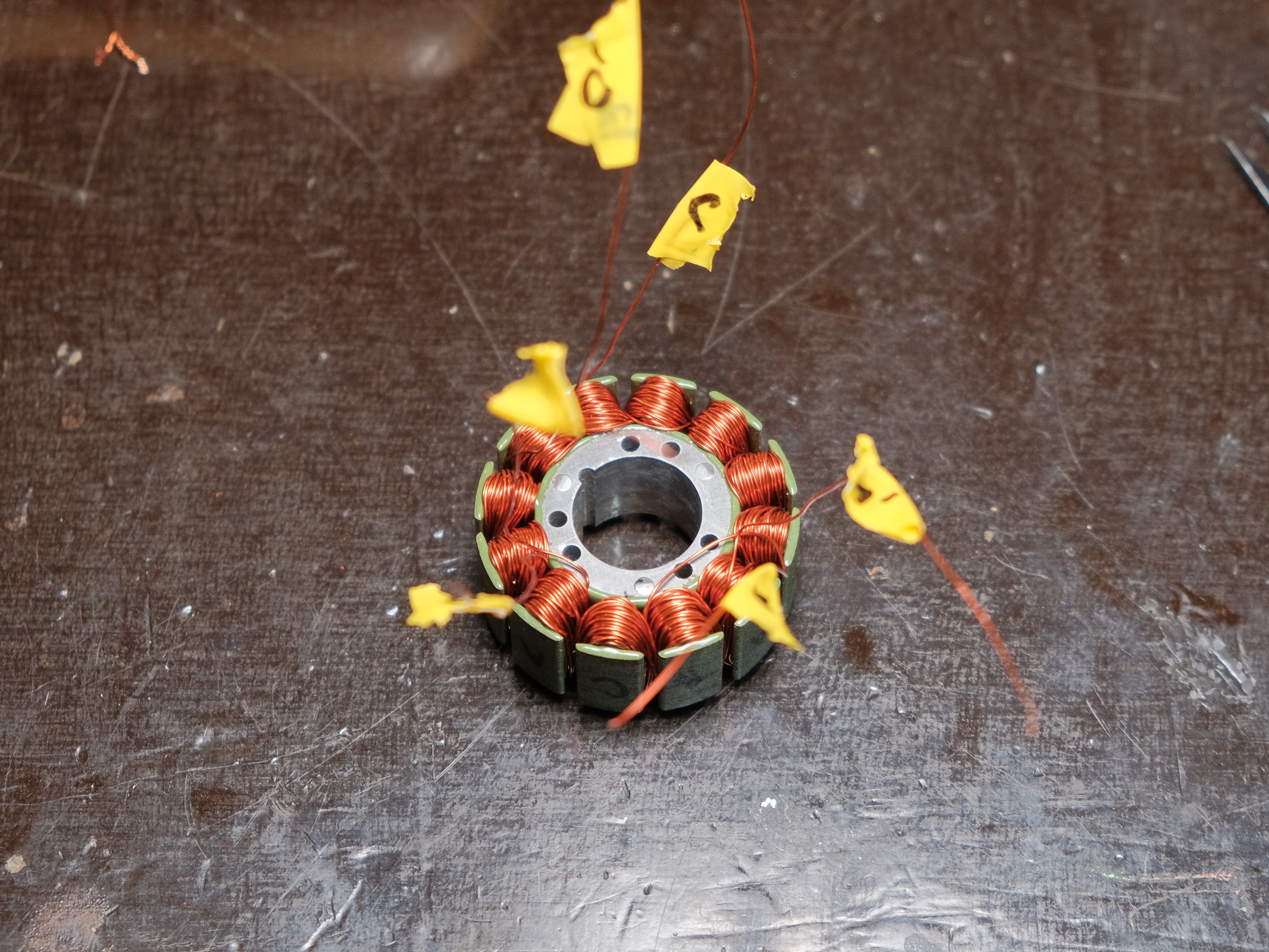
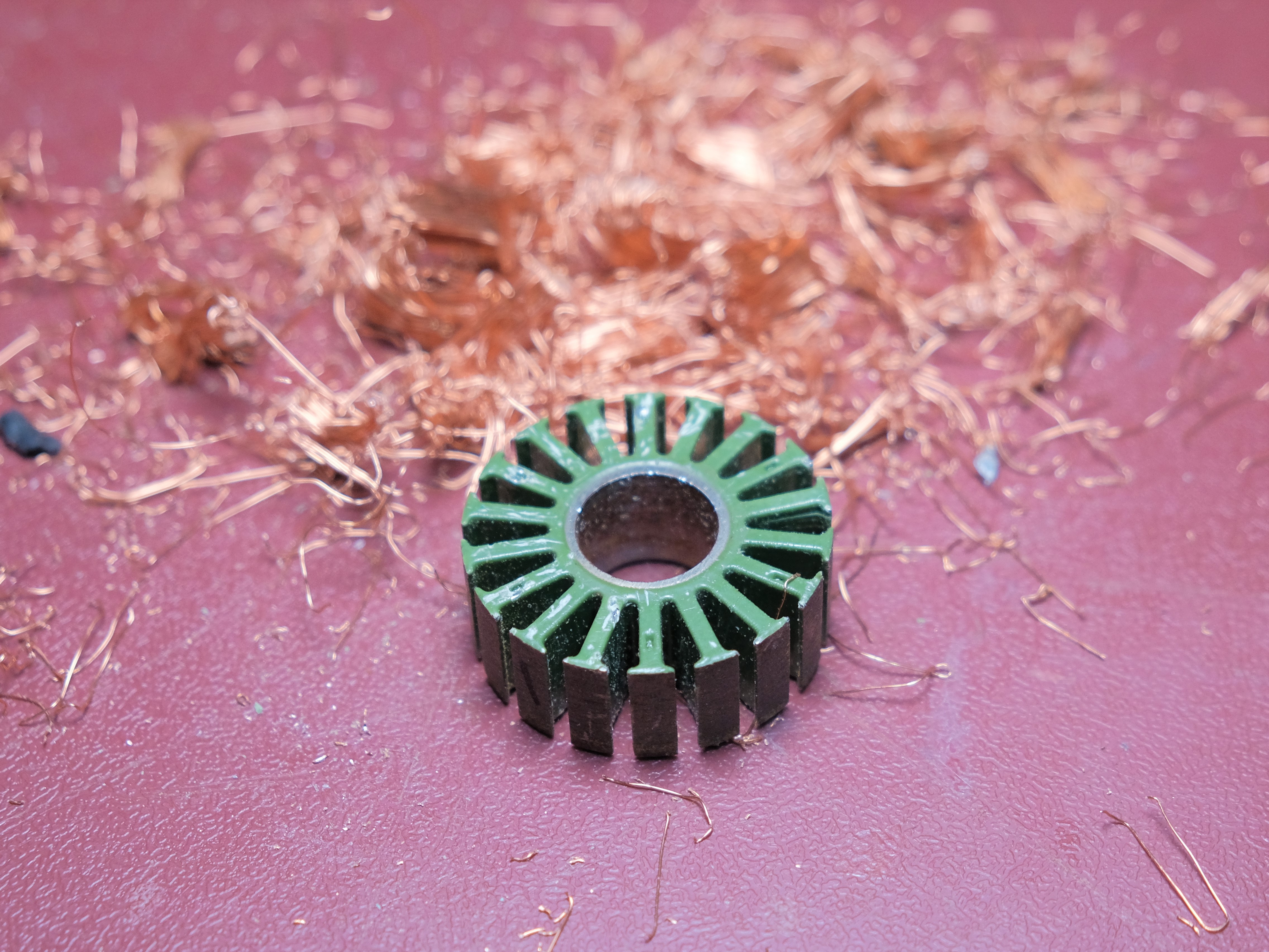
I also rewound a 12 pole BLDC motor, salvaged from a LASER printer. This motor initially had 35 turns per pole and I was able to rewind it to 50 turns per pole. In the measurements that I made, I obtained acceptable values of current and voltage to charge lithium ion batteries of the 18650 type. In the end, I discarded it since it has a high mass due to having ceramic magnets in its external rotor.
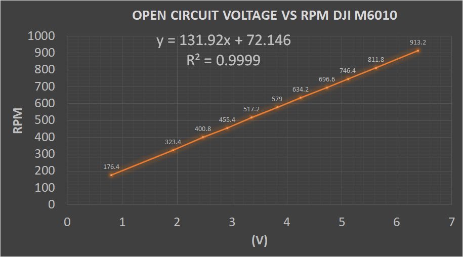
Looking for alternatives, I found 130kV BLDC motors at a good price on Aliexpress. They are motors used in the Matrice M600 drones of the DJI company. Perhaps they were discarded due to bearing wear or because this Drone is already out of production, I don't know but I do know that its capabilities as generators are exceptional.
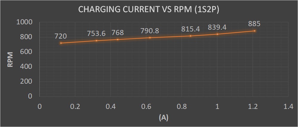
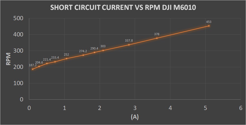
Below are the results of the measurements I made. My conclusions from these measurements are as follows:
• They deliver a lot of current even at low RPM. In the measured range, the short-circuit current had a linear growth behavior as a function of the RPM.
• It was verified that they are 130KV motors (revolutions per volt) as can be seen in the trend adjustment equation. To obtain voltages of 5 V or more, more than 600 RPM is required, which leads to the redesign of the generator blade to operate at higher RPM.
• At approximately 840RPM, a charging current of 1A is obtained in an 18650 cell, which exceeds the generation capacities of the stepper motor at the same RPM.
I can tell you that I have already finished the first variant of the Generator Hub (BLDC M6010) and I am now working on the redesign of the new Blade with the GPL software QBlade 0.96.
Greetings to all
![]()
![]()
![]()
![]()
![]()
![]()
![]()
![]()
![]()
![]()
-
MEASUREMENTS TO THE GENERATOR, RESULTS AND CONCLUSIONS
05/05/2022 at 17:58 • 0 commentsDuring the field tests on prototype 1, the maximum voltage value obtained in the internal capacitor was approximately 22V. The wind speed recorded that day was 22km/h, with gusts of 26-28km/h.
In the lab, if we spin the generator rotor until we get that 22V, we could measure the maximum RPM reached during the field tests. Other values of electrical magnitudes could be determined to try to characterize the nema 17 stepper motor in its role as generator in this Wind Turbine.
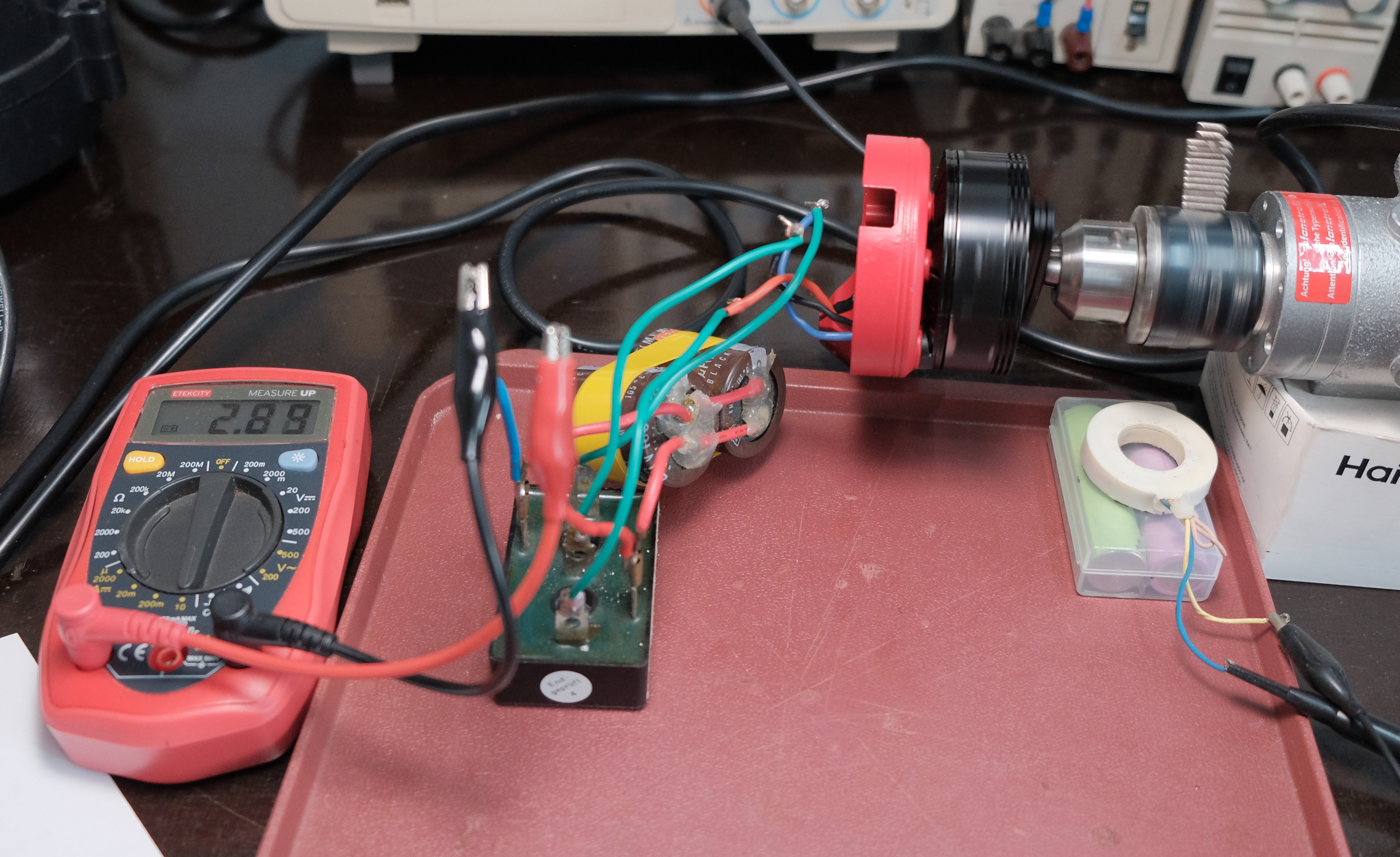
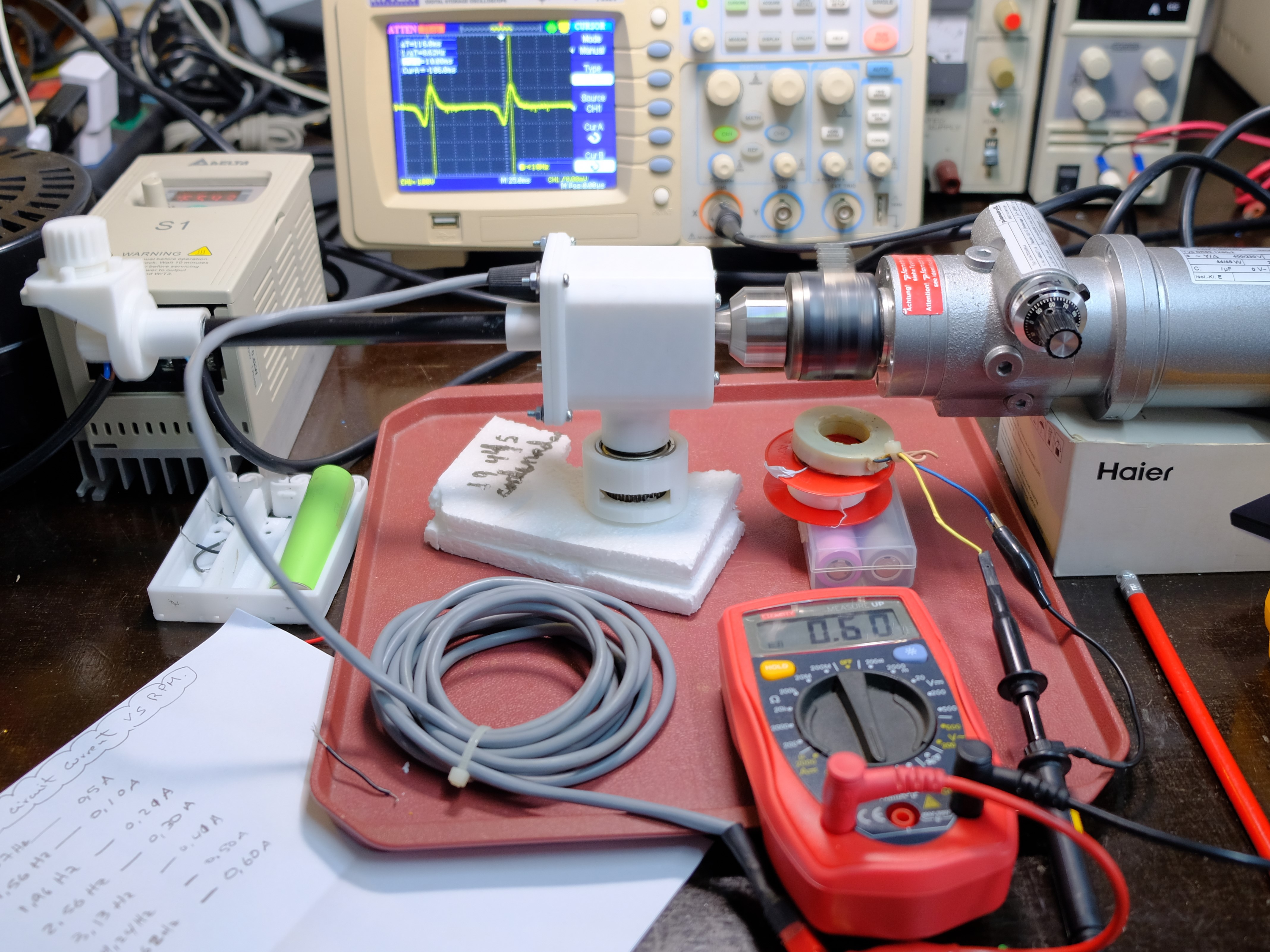
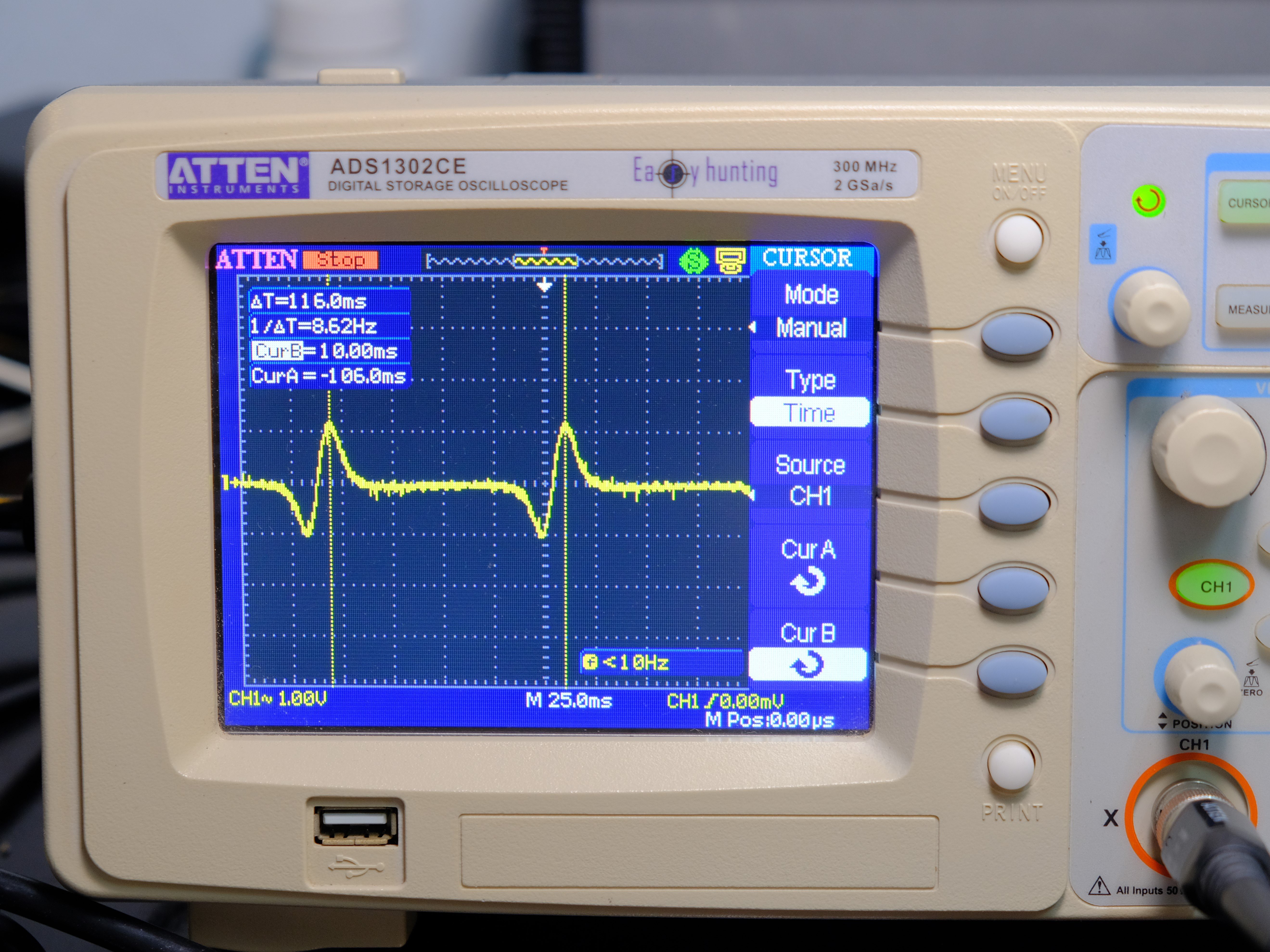
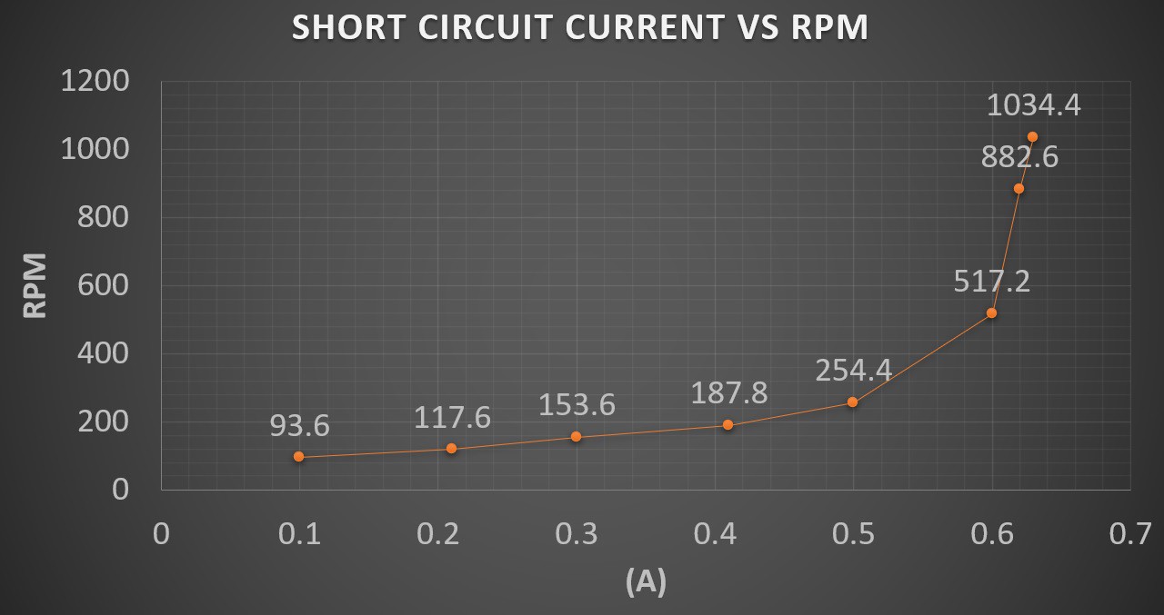
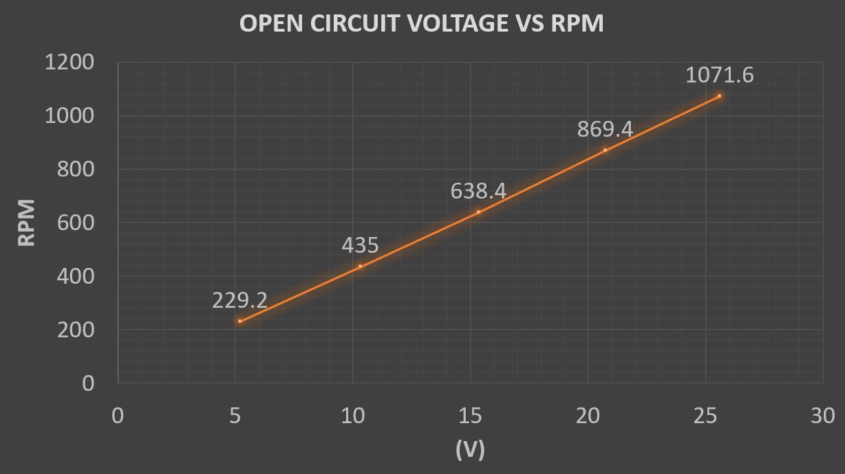
To carry out the experiments, a three-phase induction motor was used, which could vary the frequency of the supply current with a Variable Frecuency Drive (VFD) and with it, the RPM of its operation. This motor was attached to the chuck of a drill with which the generator shaft would be fixed. Attached to this mandrel was a small magnet that would pass close to a 2000-turn coil of fine gauge wire, when the entire assembly rotate. This coil would be connected to the signal input of an oscilloscope where pulses would be detected. Measuring the time elapsed between pulses with the same phase and determining its reciprocal, the frequency expressed in Hertz (Hz) would be determined. In turn, a multimeter would be placed at the generator output and the voltage and current would be measured based on the RPM. At the end graphs of dependency of these magnitudes based on the RPM would be generated. One area of interest was determining the best series-parallel configuration of 18650 lithium cells to be charged by the generator. Two 1500mAh 18650 cells balanced at a voltage of 3.7V were used in the experiments. Conclusions:
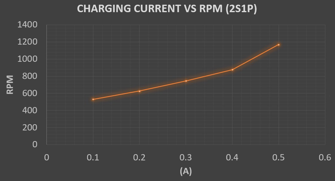
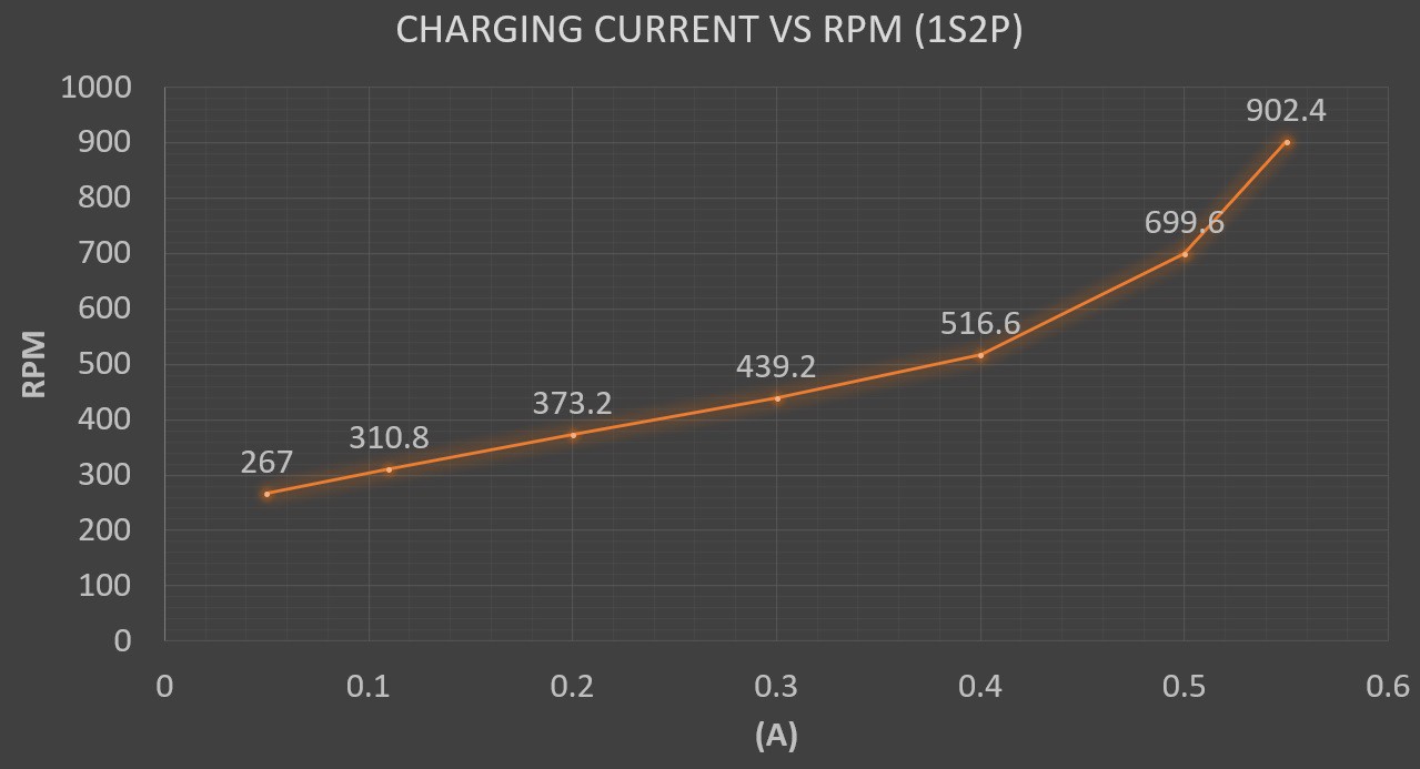
• The nema 17 stepper motor (generator) apparently is not capable of supplying a short-circuit current greater than 0.65 A. From 500 RPM, a pre-limit value of 0.6A is obtained.
• The 22V obtained during the field tests correspond to about 870 RPM of the generator. Typical values would be between 500-700 RPM.
• The open circuit voltage has a linear behavior as a function of RPM. At 600RPM approximately 14.5V is obtained.
• At typical 700 RPM you get 0.5A charging current on a 1S2P 18650 system, versus approx 0.26A on a 2S1P 18650 system.
• It makes no sense to use configurations of three or more 18650 cells in series. High RPMs are required that this wind turbine could hardly reach.
This is all for now, tell me your opinion!![]()
![]()
![]()
![]()
![]()
![]()
-
ORGANIZATION OF THE STL FILES TO PRINT
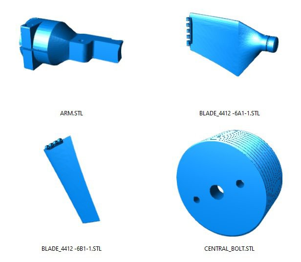
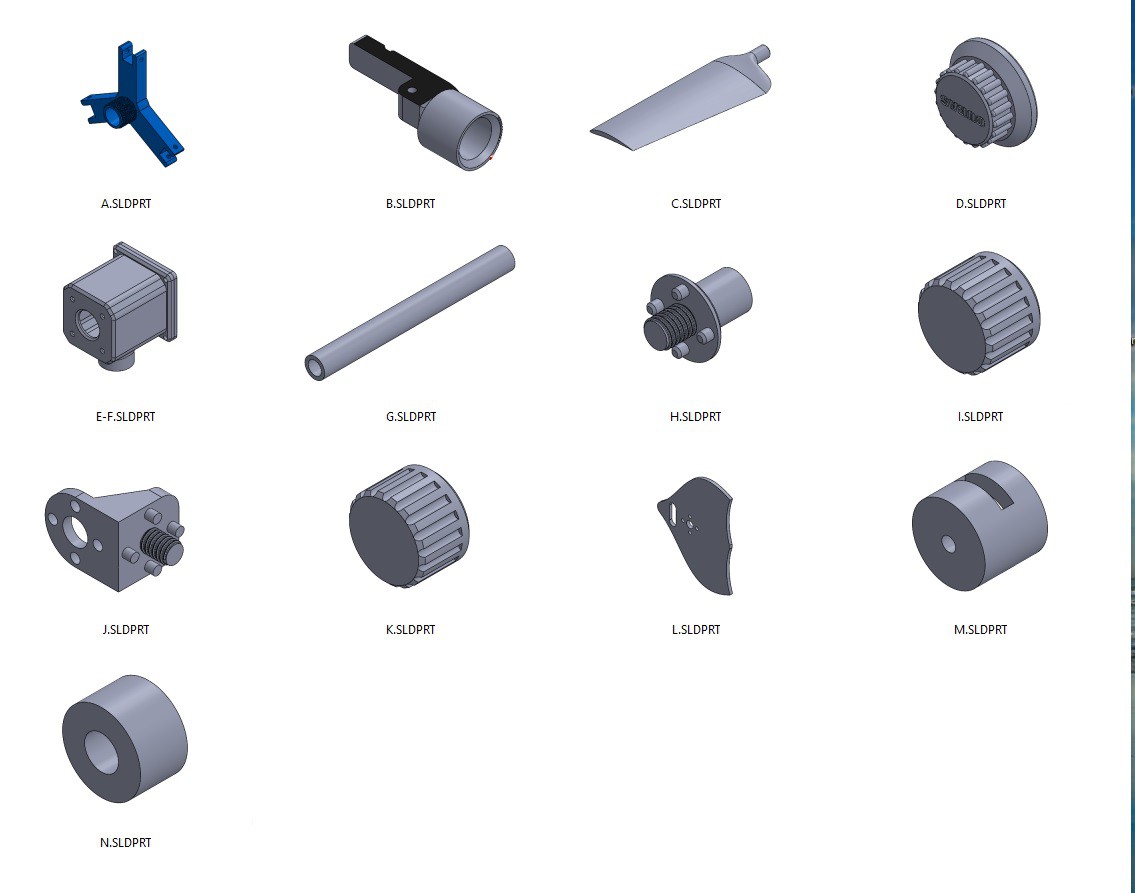
05/01/2022 at 16:07 • 0 commentsWhen I uploaded the STL files to the Files section for the first time I forgot one piece. Now I have named the STL files with letters consecutively. I have also included an image showing each piece and its corresponding letter. Nut I and K are not the same, although they look the same externally, keep this in mind!
The L part does not necessarily have to be 3D printed. I have found it feasible to cut it with a laser cutter or a CNC. I have included the DXF file of this piece.Part G can be replaced by a standard tube of that size and would avoid the need to print it.
![]()
 adriancubas