The ESP32 firmware for the charge controller can be found on my Github Account here : ESP32 firmware
From this repo, put all the fles into a directory named "JP_eSolarPanel_ESP32"
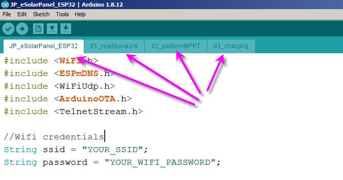
Then open the JP_eSolarPanel_ESP32.ino file. It should launch arduino IDE and open four tabs

Enter your Wifi credentials, install the required libraries and compile !
As you will see the code is rather straightforward. The only tricky parts are :
- bluetooth communication with the Android App
- Over The Air firmware update (I used the standard example !)
The 01_readSensors tab contains the code for... reading the sensors !
I do use the ESP32 ADC to measure most of the analog values we need. This ADC is far from being perfect and suffers from quite important non linearities. If order to compensate these problems I perform a multilinear correction of raw values that has been calibrated for my own ESP32 and whose values are precise on the cut off voltages of 5, 9,3 and 16.8 V thresholds.
Have a look at the Excel sheet into the github repo for more details : ADC calibration sheet
Nothing special into this tab excepted that I do not read Iout from the Buck Converter. Instead I compute it with an assumption that the total power is kept between input and output with the buck converter's efficiency ratio
Win = Iin * Vin;
  Wmin += Win;
  nbSamples++;
  Wout = Win * efficiency;  //power is almost preserved but efficiency is not 100%
The 02_performMPPT tab holds all the MPPT algorithm described previously.
Nothing to add excepted that I have implemented a fast convergence process which is quite efficient!
This is mainly based on "how far" we are from the VinMPPT voltage. If far then the step used to correct the Buck converter voltage is higher.
 if (Vin > 19.5) step = 150;                   //start fast then decrease
  else if (abs(Vin - VinMPPT) > 2) step = 100;
  else if (abs(Vin - VinMPPT) > 1) step = 20;
  else if (abs(Vin - VinMPPT) > .3) step = 8;
  else step = 1;
  if (deltaWin > 15) step = 1;              //if power is oscillating too fast (20%), slow down
 if ((outputMode != MPPT)&&  (abs(VoutMax - Vout) < 3.0))  step = 1;
I must admit that this part of the code was tuned quite empirically... but it works really well on my panel !
Finally in order to cope with shadows or cloud I force the reset of this process every minutes :
if ((millis() - MPPTchanged) > 60000)           //force a refresh every minute
  {
    dutyCycle -= 10;                             //decrease; //avoid staying into local minimum
    WinMPPT = 0;
    MPPTchanged = millis();
    Serial.println("local min ");
    TelnetStream.println("local min ");
  }
The 03_charging tabd handles all the logic of charge for the various modes
For example the Solar charge mode is quite simple and implements a classical constant current / constant voltage logic.
 case SOLAR_CHARGER:                                     //charger mode MPPT & CC-CV CHARGING ALGORITHM
      if (Iout > IoutMax) dutyCycle += step;                         //Current Is Above → decrease current
      else if (Vout > VoutMax) dutyCycle += step;                    //Voltage Is Above → decrease voltage
      else performMPPT();                                            //tab #02
      if ((Vout > VoutMax) && (Iout < IoutMax * 4. / 100.))
      {
        VoutMax = VbatteryFloat[myBattery];                          //switch to float charging mode
      }
      break;
I still have to polish this code for the end of charge when going to float mode for lead Acid of to cut off the charge for lipo.
Currently this is implemented by the same piece of code simply with different cut off thresholds (tab0) :
enum typeBat {ACID_12V, LIPO_1s, LIPO_2s, LIPO_3s, LIPO_4s};
int  myBattery = LIPO_3s ;
float VoutMax = 0.;                                    // Maximum voltage output of charger (including .3V ideal diode drop out
float IoutMax = 0.;                                    // Maximum current output of charger
float VbatteryMax[]       = {15., 4.5, 8.7, 12.9, 17.1};    //   USER PARAMETER - Maximum Battery Charging Voltage (includes .3V diode drop out)
float VbatteryFloat[]     = {14.4, 3.3, 6.3,  9.3, 12.3};   //   USER PARAMETER - Minimum Battery Charging Voltage (includes .3V diode drop out)
float Icharge[]           = {5.0,  1.0, 2.0,  3.0, 4.0};    //   USER PARAMETER - Maximum Charging Current
 JP Gleyzes
Discussions
Become a Hackaday.io Member
Create an account to leave a comment. Already have an account? Log In.