The "maths" of this project could be quite complex but clever people published the most difficult parts : sun equations
I do use two different codes to compute sun position but hopefully these codes give the same results !
- first one is into my Android "companion App". The heart on the computations can be found here : astro_library,
- second one is the arduino library solarCalculator which is running into the ESP32 firmware of the Solar Tracker.
Both do more or less the same job, they provide functions to calculate the times of sunrise, sunset, solar noon, twilight (dawn and dusk), Sun's apparent position in the sky, equation of time, etc.
I do only use the solar position at a given time and at a given position on the earth.
Knowing the Sun angles (elevation and azimut) we have now to "translate" them into "number of steps" to be applied to each stepper motor on the Solar Tracker.
Let's start by the simpler: azimut
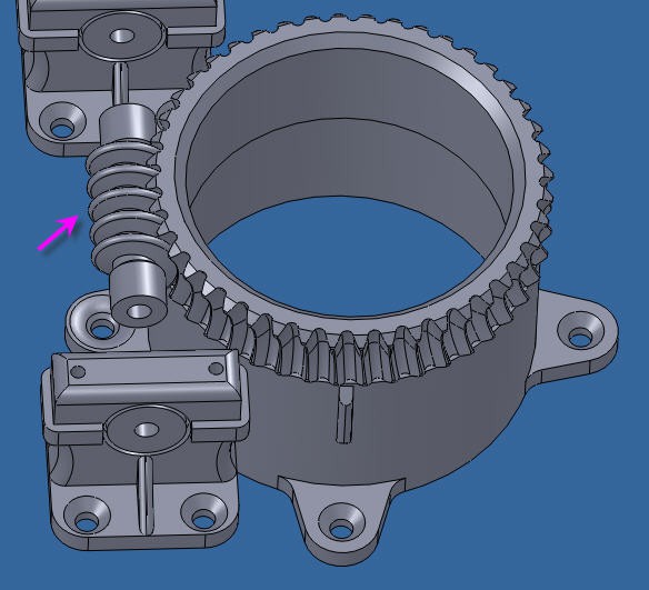
Azimut motor is directly driven by a vertical axis. One full rotation of the worm Gear induces a rotation of one tooth of the vertical gear.

the motion of the azimut motor is thus really simple :
stepsToMoveAz = ((currentAz - previousAz) * wormGearRatioAz * stepsPerTurnAz) / 360;        //it's an integer
    currentAz = previousAz + (float)stepsToMoveAz * 360. / (wormGearRatioAz * stepsPerTurnAz);  //so needs to recompute real Az value
three parameters are needed:
float wormGearRatioAz = 44.0;
int stepsPerTurnAz = 200;
#define SOLAR_PANEL_R 540   //expressed in mm
basically, the number of teeths of the azimut gear and the number of steps per turn for the stepper plus the panel width. Easy!
Now the elevation is a little more tricky
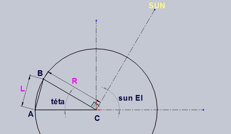
Elevation axis is actuated by the linear leadscrew. The motion is depicted on this drawing

where
- C is the center of motion (bottom long axis of the panel where are located the hinges)
- A is the top plate where is fixed the elevation stepper motor
- B is the top of the panel where is located the leadscrew hinge
The sun is on the top right corner and we want it to be perpendicular to the panel (BC)
- BC = R is thus the width of the panel
- A has for coordinates (R, 0)
- B has for coordinates (R.cos(téta), R.sin(téta)
we want to compute L = distance(A, B)
L^2 = (xB - xA)^2 + (yB - yA)^2
Thus
L = Sqrt((xB - xA)^2 + (yB - yA)^2)
L = Sqrt( (R.cos(téta) - R)^2 + (R.sin(téta) - 0)^2)
L = Sqrt( R^2.cos^2(téta) + R^2 -2.R^2cos(téta) +R^2;sin^2(téta))
L = Sqrt( 2.R^2 -2.R^2cos(téta))
and as cos(téta) = sin( Sun_El)
L = R. Sqrt(2 - 2.sin(sun_El))
This equation is directly implemented into the firmware
//length = R* sqrt(2 -2sin(sun_El))
    previousElLength = SOLAR_PANEL_R * sqrt(2 - 2 * sin(previousEl * pi / 180));
    currentElLength = SOLAR_PANEL_R * sqrt(2 - 2 * sin(currentEl * pi / 180));
This being done, we just have to convert the length into steps:
stepsToMoveEl = ((currentElLength - previousEl
Length) * wormGearRatioEl * stepsPerTurnEl) ;     //it's an integer
currentElLength = previousElLength + (float)stepsToMoveEl / (wormGearRatioEl * stepsPerTurnEl); //so needs to recompute real currentElLength value
currentEl = 180. / pi * asin(1. - pow(currentElLength / SOLAR_PANEL_R, 2) / 2.);
                 //and real El value
and we need two other paremeters for this:
float wormGearRatioEl = 1.0 / 0.8;                  //for M5 thread, 0.8mm per turn
int stepsPerTurnEl = 200;
If you build your own Solar Tracker with the same Azimut/Elevation axis you should only have to verify these formula and tune the parameters to your own setup.
 JP Gleyzes
Discussions
Become a Hackaday.io Member
Create an account to leave a comment. Already have an account? Log In.