Let's have a closer look at the geometry of the Azimut axis
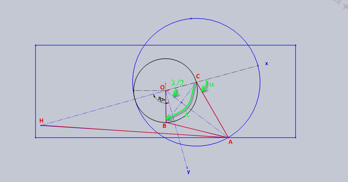
- H, O and C are aligned on the x axis of our frame centered in O
- OC = OB = R
- BA = CA = 2R
- alpha is the angle of rotation of the right CA arm
- lambda is the angle of rotation of the crank around its center O
We have:
and
These two equations link the rotation of the arm to the rotation of the crank and give the length of the linear actuator.
alpha varies from 0 to 180° while lambda varies from 0 to 360°.
The rotation of the crank is directly proportional to the orientation of the panel. Let's fix one more degree of freedom. Assume that when alpha = 120°, lambda = 180° and we also have the panel pointing to the south.
That is Azimut Az= 180°.
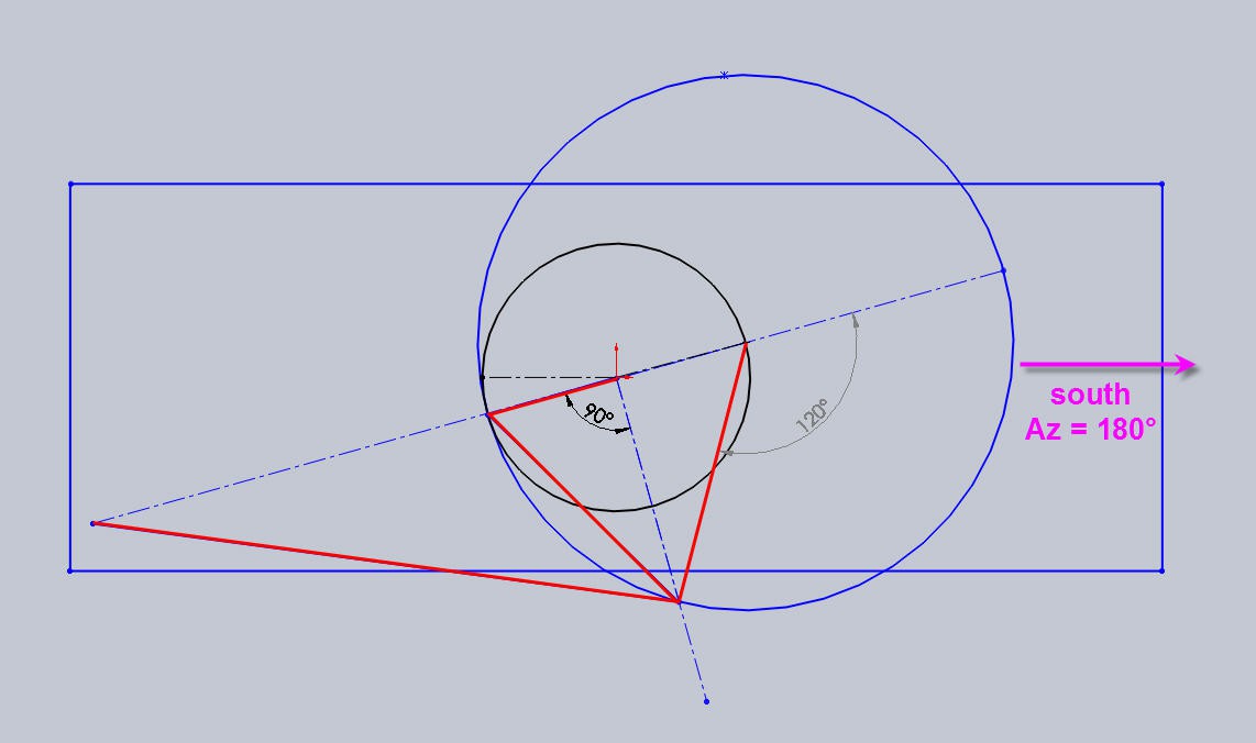
We can now use Excel to look at the curves of motion.
We have this curve when plotting lambda as a function of alpha
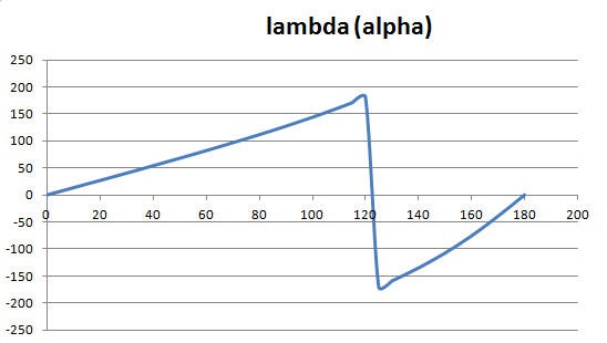
The discontinuity at 180° is normal and can be avoided by adding 360°
Thus we can plot the reverse curve alpha as a function of lambda and knowing that Az = 360 - lambda, we can get the curve alpha as a function of Az.
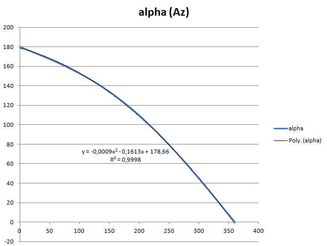
This curve is obviously non linear. It could be mathematically computed, but it can also be nicely aproximated by a degree 2 polynomium. And as I am lazy and Excel does this very well alone, we even get this equation!
Finally we can also have a look at the motion of the linear actuator as a function of alpha.
We can see that when the two moving arms are too close the motion will be very inefficient. Useful range would be for alpha between 30 to 150° ("linear" portion of this curve).
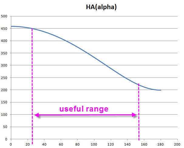
Nevertheless, even with this "limited" range, our rotation (lambda) will be far above 180°. This was my target!
We will test all this after modification of the code to implement these equations into the firmware.
 JP Gleyzes
Discussions
Become a Hackaday.io Member
Create an account to leave a comment. Already have an account? Log In.