JP Gleyzes
-
the end of day flip
08/29/2022 at 07:44 • 0 commentsAt the end of the day the panel should go back to next morning position.
Here is how it works: (timelapse speed increased by 120)
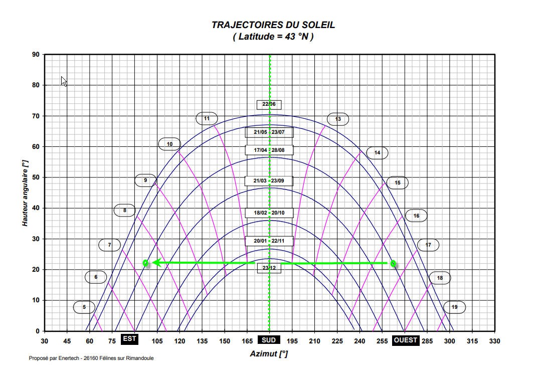
As you can see the panel stops its motion when elevation of the sun reaches a "home" value and goes back to East when sun elevation reaches a "limit" value.
The computation for the "flip" is quite simple as the panel has simply to go to the symetrical position (compared to the current one). The symetry is of course to the max elevation angle which is at 12:00 solar time.
switch (heliostatStatus) {

      case tracking:    // now go to next morning sunrize azimuth
        heliostatStatus = morning ;
        currentAz = 180 - (previousAz - 180.0);
        stepsToMoveAz = ((currentAz - previousAz) * wormGearRatioAz * stepsPerTurnAz) / 360;        //it's an integer
        currentAz = previousAz + (float)stepsToMoveAz * 360. / (wormGearRatioAz * stepsPerTurnAz);  //so needs to recompute real Az value
        Serial.println("going to next morning Az");
        break;

      case morning:    // now go to sleep until tomorrow morning
        heliostatStatus = sleeping ;
        sunRize = 2 * ((hours - 12) * 3600 + minutes * 60) ;        // sunRize duration symetrical around 12h and "now"
        timeToSleep = 86400 - sunRize;
        esp_sleep_enable_timer_wakeup(timeToSleep * uS_TO_S_FACTOR);
        Serial.print("timeToSleep : ");
        Serial.println(timeToSleep);
        stepsToMoveAz = 0;
        break;

      case sleeping:    // don't move
        stepsToMoveAz = 0;
        break;
    }
The automat goes from "tracking" to "morning" and then "sleeping"
When in "morning" status it computes the symetrical azimut to noon and the time to sleep before getting this azimut. Then it goes to deepsleep state.
![]()
On the video (08/29/2022) it was 18:45 pm local time. That is 16:45 UTC when the sun got the 22° elevation limit. Then the panel had to flip to 7:15 am UTC (green point with same sun elevation).
These Sun Elevation values are currently constant into the code:
#define EL_HOME 23          //expressed in °
#define EL_LIMIT 22         //expressed in °
It could be nice to have them as parameters to adapt to your local configuration (natural horizon mask of your field).
This will be done into a next release of the codes (firmware + companion App)!
-
Trying AI to design a splashscreen image
08/28/2022 at 11:52 • 0 commentsMy son tried to design a nice splashscreen image for the project.
He made several attempts using midjourney's AI power. And the results are quite impressive!
- Post apocalyptic one:
![]()
- Honeycomb style:
![]()
- Eco Style: (my favorite)
![]()
- more landscape:
![]()
- even more landscape:
![]()
- chicken and egg dilemma:
![]()
chicken and egg tracking:
![]()
Tell me which one you prefer!
-
testing testing and retesting
08/27/2022 at 08:17 • 0 commentsMy latest modification of the software introduced quite a lot of necessary improvements but also some complexity into the code and thus bugs occured...
The reason for these bugs were simply a lack of tests... The system was running under "normal" conditions but was critically failing when a "degraded case" occured.
So the only solution was to improve (a lot) the testing scenarii and harden the software side.
I took my inspiration from the European Space Standards (I am a space ingeneer !) and taylored the ECSS-E-ST-40C which is the "Verification Standard" for space systems !
Stop kidding, I only kept from this standard the overall philosophy consisting in documenting and testing the specifications under realistic use cases including degraded modes of the software.
Here are the testing cases that have been currently checked:
- initialization of tracker (time and location) with Bluetooth
- initialization of tracker (time, location and wifi credentials) with Bluetooth
- running the system with bad wifi credentials, no credentials, good credentials...
- initialization of tracker (time and location) with Bluetooth + Wifi
- initialization of tracker (time only) with Wifi
- initialization of tracker (test) with no Wifi nor Bluetooth
- initialization of tracker during day (with or without wifi and bluetooth)
- initialization of tracker during night (with or without wifi and bluetooth)
- system running in normal conditions with wifi
- system running in normal conditions with bluetooth
- system running in normal conditions without bluetooth and Wifi, only with the Real Time Clock of the board
- system running in normal conditions, detection of "night" and repositioning to morning next day
- system running in normal conditions, resume of operation next morning next day
- system running with a lack of power (lion battery only)
- initialization of tracker with lack of power (lion battery only)
- charging of a 1s lipo (check CV/CC algorithm and end of charge conditions)
- charging of a 2s lipo (check CV/CC algorithm and end of charge conditions)
- charging of a 3s lipo (check CV/CC algorithm and end of charge conditions)
- charging of a 4s lipo (check CV/CC algorithm)
- charging of a lead acid battery (check CV/CC algorithm and end of charge conditions)
- running in PSU mode (check constant voltage)
- running in MPPT mode (check max power produced by MPPT algorithm)
- check reverse voltage protection when no sun on the panel
- and finally: long duration test. Several days of operations in "debug mode"
Nothing fancy into this log... All these tests needed a lot of time, but they were the price to be paid to get confidence into the system.
It's now fully automatic, without any need for human intervention (initialization excepted).
It can work with or without sun, relying only on the sun angles computation and a sufficient (or not) voltage to run the motors.
All the complexity is hidden into an intensively tested software system.
-
funny "morning bug"
08/24/2022 at 13:56 • 0 commentsHere is a funny bug of my Solar Tracker.
I was testing the automatic failsafe conditions of time initialization.
Due to a bug, the panel thought it was the very morning and made an unexpected "go to East" flip. Then it started to follow the sun but on the opposite direction (~180° azimuth off) !
Will be corrected into the next release of the code. It is not affecting the current version of the code published on my Github
This video can however be used to display the "return to East" that should occur at night!
It's a timelapse video with an increased speed by a ratio 120, it was a quite windy day, the panel is shaking a little, but works !
-
Automating the solar tracker initialization
08/22/2022 at 13:02 • 0 commentsI had to face several "difficulties":
- my solar tracker is intended to be used as a mobile device. But when moving your location moves also and thus the solar angles computation may drift a little. GPS coordinates should be updated into the ESP32 board whenever you change location. Particularly when the panel is used into a camper van...
- my solar tracker firmware needed Wifi to get the time over ntp server... This wasn't a good idea for a camper van (although it could work using your smartphone as a hotspot... but not really practical).
I had thus to find a way to overcome these issues...
I already had an Android App to help position the panel face to the sun. My ESP32 has also Bluetooth Low Energy... Seemed simple to add a BLE connection between phone and ESP32 to communicate the time and the location to the board.
This is exactly what I did, but it wasn't as simple as expected !
My specs were:
- avoid any "binding process" between phone and ESP32. Everything should be fully automatic
- try to connect to wifi on ESP32 and get the time over NTP. This shouldn' be a blocking process in case of a noWifi area
- allow BLE connection on the ESP32 while broadcasting (notifying) over BLE
- allow the time and position to be sent from phone when BLE is connected
- keep the BLE connection open while the Android App is running, go to deepsleep as soon as possible to save energy on the ESP32 board
- keep the nice feature of calibrating the panel position to a fast and easy start up on any new location at any time
- go on working on internal RTC clock if no wifi or no BLE link is available
Here is the result, with an extremely simple operationnal procedure:
- launch the companion App and position the panel as explained into this log
- when the panel is properly facing the sun, simply push the reset button of the ESP32 board
- quit the App
That's it !
I moved the phone to track the sun and at the end of the video I pushed the reset button of the ESP32.
Have a look at the bottom of this screen to see the automatic handshake between phone and board.
![]()
Several tricks are used to allow this simple behavior :
ESP32 allows to detect the boot condition. I did detect if it is a "reset boot" or not (deepsleep in this case).
esp_sleep_wakeup_cause_t wakeup_reason;
  wakeup_reason = esp_sleep_get_wakeup_cause();

  switch (wakeup_reason)
  {
    case ESP_SLEEP_WAKEUP_EXT0 : Serial.println("Wakeup caused by external signal using RTC_IO"); break;
    case ESP_SLEEP_WAKEUP_EXT1 : Serial.println("Wakeup caused by external signal using RTC_CNTL"); break;
    case ESP_SLEEP_WAKEUP_TIMER : Serial.println("Wakeup caused by timer"); break;
    case ESP_SLEEP_WAKEUP_TOUCHPAD :
      Serial.println("Wakeup caused by touchpad");
      touchWake = true;
      break;
    case ESP_SLEEP_WAKEUP_ULP : Serial.println("Wakeup caused by ULP program"); break;
    default :
      Serial.printf("Wakeup was not caused by deep sleep: %d\n", wakeup_reason);
      resetWake = true;
      break;
  }
If it is a reset boot, then I do try to establish the Bluetooth link and wait 10s for it. If not (deepsleep boot) I simply try to get ntp time and if it fails I do use the RTC clock.
Be aware that RTC clock is not very accurate... So it will be a good idea, from time to time, to resync the time either with a permament Wifi connection or with the smartphone. With only the RTC internal clock you could expect several seconds of drift per day. This will not be an issue for our application as time is only used to point the panel to the sun...a few degrees of misalignement wouldn't affect too much the sun harvesting process.
Here is what says Expressif 's documentation :
ESP32 uses two hardware timers for the purpose of keeping system time. System time can be kept by using either one or both of the hardware timers depending on the application’s purpose and accuracy requirements for system time. The two hardware timers are:
- RTC timer: This timer allows time keeping in various sleep modes, and can also persist time keeping across any resets (with the exception of power-on resets which reset the RTC timer). The frequency deviation depends on the RTC Timer Clock Sources and affects the accuracy only in sleep modes, in which case the time will be measured at 6.6667 μs resolution.
- High-resolution timer: This timer is not available in sleep modes and will not persist over a reset, but has greater accuracy. The timer uses the APB_CLK clock source (typically 80 MHz), which has a frequency deviation of less than ±10 ppm. Time will be measured at 1 μs resolution.
Here is how the time is computed from the last saved value (hours, minutes, seconds et tvsec) and knowing the seconds elapsed since reboot (current_time.tv_sec) :
else if (!resetWake)
  {
    Serial.println("time from RTC :");

    struct timeval current_time;
    gettimeofday(¤t_time, NULL);
    Serial.printf("seconds : %ld\nmicro seconds : %ld", current_time.tv_sec, current_time.tv_usec);

    int sec  = seconds - tvsec + current_time.tv_sec ;
    sec = hours * 3600 + minutes * 60 + sec;
    int ss = sec % 60;
    sec = sec / 60;
    int mm = sec % 60;
    sec = sec / 60;
    int hh = sec % 24;
    int dd = days + sec / 24;

    //set time manually (hr, min, sec, day, mo, yr)
    setTime(hh, mm, ss, dd, months, years);
    Serial.print("\ntime: ");
    display_time();
  }
Finally if the reset button has been pressed, we use this information to avoid moving the panel (supposed to be pointing to the sun) and go directly into deepsleep.
 if (resetWake == true)  //reset was done. Calibration of panel is acquired. Don't move

  {
    Serial.println("calibration of panel done, no motion and goto to sleep");
    stepsToMoveEl = 0;
    stepsToMoveAz = 0;
  }
I forgot to mention that the "three dots menus" on top right of the App allows to send Wifi Credentials to your ESP32 board when you are close to a wifi router.
Afterwhat the process will remain fully automatic: a wake up every ten minutes, try to get the ntp time and move the panel accordingly to sun position.
-
Panel Orientation App
07/27/2022 at 10:02 • 0 commentsI finally coded a small Android Application to help to position the solar panel and thus avoid calibration of the solar tracker !
Very simple to use:
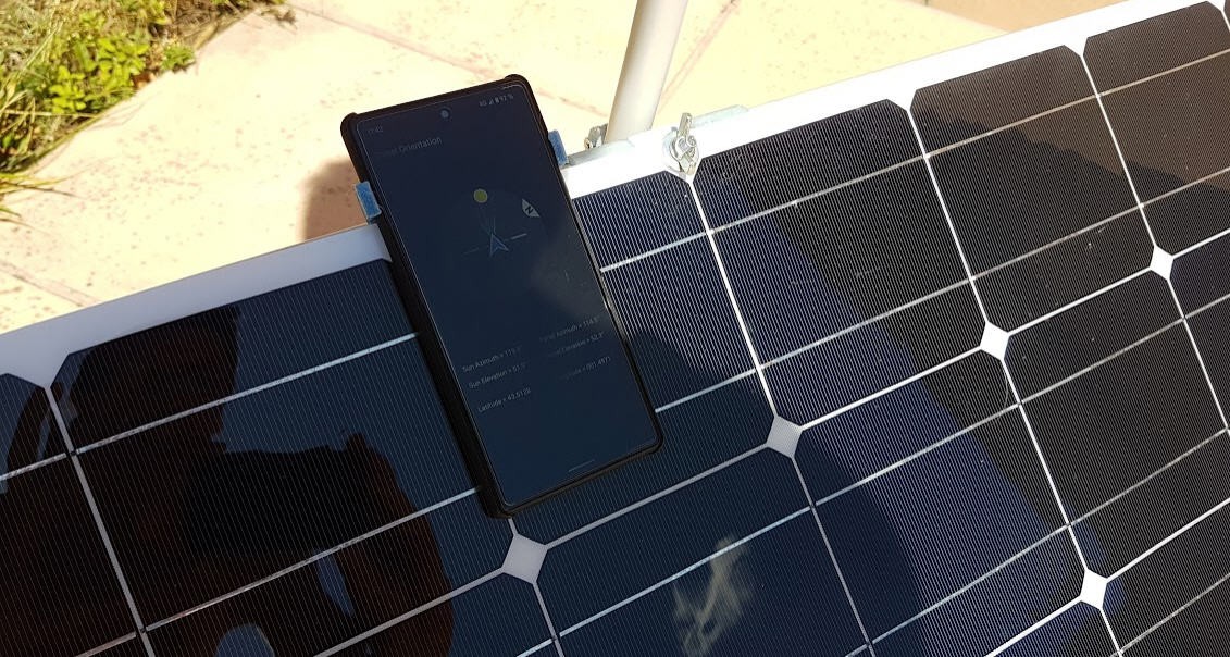
- attach the smartphone on the panel using the 3D printed holder (or manually !)
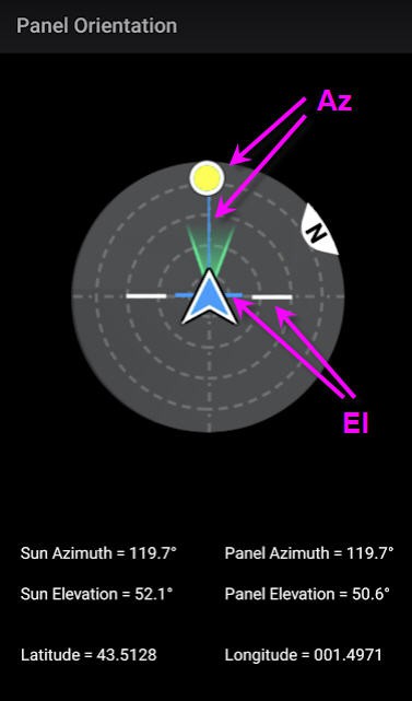
- align the sun symbol to the blue line (azimuth orientation)
- align the blue horizontal bar with the two horizontal white ones
![]()
![]()
and that's it !
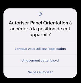
The app needs to know your position to compute solar angle at your location. So GPS permission is required...
![]()
- Source code is available on my github page
- Compiled Application (.apk file) is available here
- And the 3D printed phone holder is here
-
Gerber files
07/12/2022 at 10:32 • 0 commentsTo publish the gerber files I followed this tutorial from Sparkfun
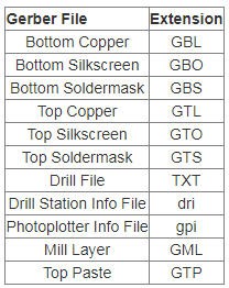
The gerber files available are :
![]()
The files are available here.
-
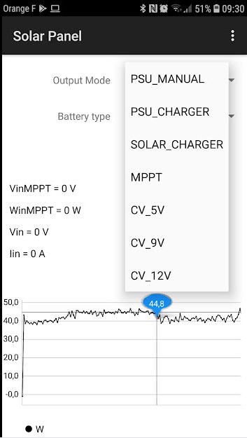
MPPT Solar Panel Controller : Android App
06/18/2022 at 06:54 • 0 commentsThe Android App is simply used to monitor and control the ESP32 firmware.
![]()
This App is written in Basic4Android. This language is very close to .Net language and offer a really powerful way to write Android (or IOS) application in no time.
The full project is available on my github page into this .zip file
But before opening this file you should install the B4X environment on your computer. Don't be afraid this is easy to do and all you have to do is to follow precisely these instructions : B4A installation
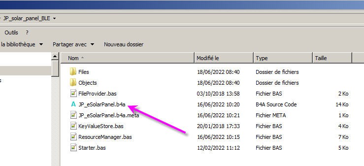
Then unzip the project and you should see something like this :
![]()
Doule click on the .b4a file and the project will open into the IDE
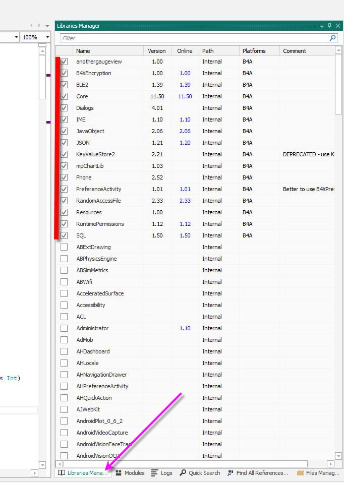
Before compiling the code don't forget to add these library (download them and tick the box)
![]()
You will need to get familiar with basic usage of B4a. This help page will be precious!
Finally you will be able to compile the code and install the .apk on your phone.
And if you don't have time to compile the source code then here is the Android .apk file
-
MPPT controller : ESP32 firmware
06/16/2022 at 08:59 • 0 commentsThe ESP32 firmware for the charge controller can be found on my Github Account here : ESP32 firmware
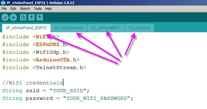
From this repo, put all the fles into a directory named "JP_eSolarPanel_ESP32"
Then open the JP_eSolarPanel_ESP32.ino file. It should launch arduino IDE and open four tabs
![]()
Enter your Wifi credentials, install the required libraries and compile !
As you will see the code is rather straightforward. The only tricky parts are :
- bluetooth communication with the Android App
- Over The Air firmware update (I used the standard example !)
The 01_readSensors tab contains the code for... reading the sensors !
I do use the ESP32 ADC to measure most of the analog values we need. This ADC is far from being perfect and suffers from quite important non linearities. If order to compensate these problems I perform a multilinear correction of raw values that has been calibrated for my own ESP32 and whose values are precise on the cut off voltages of 5, 9,3 and 16.8 V thresholds.
Have a look at the Excel sheet into the github repo for more details : ADC calibration sheet
Nothing special into this tab excepted that I do not read Iout from the Buck Converter. Instead I compute it with an assumption that the total power is kept between input and output with the buck converter's efficiency ratio
Win = Iin * Vin;
  Wmin += Win;
  nbSamples++;
  Wout = Win * efficiency;  //power is almost preserved but efficiency is not 100%
The 02_performMPPT tab holds all the MPPT algorithm described previously.
Nothing to add excepted that I have implemented a fast convergence process which is quite efficient!
This is mainly based on "how far" we are from the VinMPPT voltage. If far then the step used to correct the Buck converter voltage is higher.
 if (Vin > 19.5) step = 150;                   //start fast then decrease
  else if (abs(Vin - VinMPPT) > 2) step = 100;
  else if (abs(Vin - VinMPPT) > 1) step = 20;
  else if (abs(Vin - VinMPPT) > .3) step = 8;
  else step = 1;
  if (deltaWin > 15) step = 1;              //if power is oscillating too fast (20%), slow down
 if ((outputMode != MPPT)&&  (abs(VoutMax - Vout) < 3.0))  step = 1;
I must admit that this part of the code was tuned quite empirically... but it works really well on my panel !
Finally in order to cope with shadows or cloud I force the reset of this process every minutes :
if ((millis() - MPPTchanged) > 60000)           //force a refresh every minute
  {
    dutyCycle -= 10;                             //decrease; //avoid staying into local minimum
    WinMPPT = 0;
    MPPTchanged = millis();
    Serial.println("local min ");
    TelnetStream.println("local min ");
  }
The 03_charging tabd handles all the logic of charge for the various modes
For example the Solar charge mode is quite simple and implements a classical constant current / constant voltage logic.
 case SOLAR_CHARGER:                                     //charger mode MPPT & CC-CV CHARGING ALGORITHM
      if (Iout > IoutMax) dutyCycle += step;                         //Current Is Above → decrease current
      else if (Vout > VoutMax) dutyCycle += step;                    //Voltage Is Above → decrease voltage
      else performMPPT();                                            //tab #02
      if ((Vout > VoutMax) && (Iout < IoutMax * 4. / 100.))
      {
        VoutMax = VbatteryFloat[myBattery];                          //switch to float charging mode
      }
      break;
I still have to polish this code for the end of charge when going to float mode for lead Acid of to cut off the charge for lipo.
Currently this is implemented by the same piece of code simply with different cut off thresholds (tab0) :
enum typeBat {ACID_12V, LIPO_1s, LIPO_2s, LIPO_3s, LIPO_4s}; int myBattery = LIPO_3s ; float VoutMax = 0.; // Maximum voltage output of charger (including .3V ideal diode drop out float IoutMax = 0.; // Maximum current output of charger float VbatteryMax[] = {15., 4.5, 8.7, 12.9, 17.1}; // USER PARAMETER - Maximum Battery Charging Voltage (includes .3V diode drop out) float VbatteryFloat[] = {14.4, 3.3, 6.3, 9.3, 12.3}; // USER PARAMETER - Minimum Battery Charging Voltage (includes .3V diode drop out) float Icharge[] = {5.0, 1.0, 2.0, 3.0, 4.0}; // USER PARAMETER - Maximum Charging Current -
Solar Tracker source code
05/13/2022 at 09:22 • 0 commentsI have just published the source code of the solar tracker.
You can find it on my github page here : ESP32 Solar Tracker
This code implements exactly the current status of the tracker as shown into the video
Features implemented are :
- try to connect to internet
- get the UTC time over NTP server
- compute the sun position using the excellent solar calulator library (licensed under the MIT License)
- compute the stepper motors motion
- read the power voltage
- perform the motion if the power level is enough to drive the motors
- apply a sleeping strategy (sleep 10 minutes during day or sleep the whole night)
- reset to the next morning position if needed
- sleep and wake up next time
Low cost solar panel solution (MPPT + sun tracker)
portable flexible panel + MPPT controller + solar tracker system less than 55 USD ????