JP Gleyzes
-
Calibrating the Solar Tracker
05/01/2022 at 13:41 • 0 commentsWhat is the panel Azimuth what is the panel Elevation, these are the two questions the ESP32 firmware is asking... before moving to new sun angles.
We do need a way to tell the firmware these answers. Classically any CNC machine or any 3D printer asks the same questions and implements a so call "homing strategy" using bed probes or home switches. You just move the axis one by one until you reach the home switch.
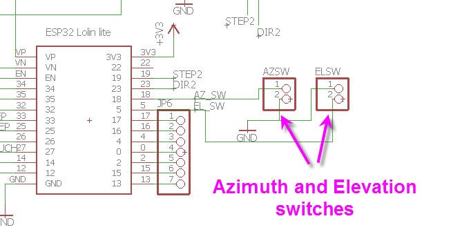
On my SolarTracker board I have thus added "home switches" headers in order to connect "switches" or any other sensor to perform homing.
![]()
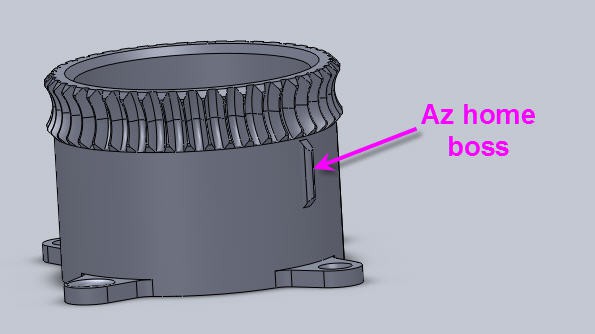
Similarly the Azimuth gear has a "boss" that could hit a switch to tell the firmware that it is at the homing position for Azimuth.
![]()
But the fact is that currently I haven't yet implemented these features... And it is not a matter of difficulty, but rather a matter of simplicity of operations !
Homing the system could be rather long as you would have to rotate Azimuth for example to the south and elevation to the max angle (70°). This could take several minutes...
I wanted something simpler and much more rapid.
For the Azimuth when you start the system it is so simple to point the panel directly to the sun.... And as my lazySusan design allows a full 360° free rotation, there is no need to fix a home point !
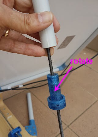
For the elevation angle you can also disengage the lead screw, you can rotate it manually in order to get the right elevation angle.
![]()
As this is working sooo well, I will even add a few more features in the software :
- modify the MPPT Androdi App to add sun angles computation and display for the current time and latitude longitude
- allow a touch pad during boot time (after manual reset) to tell the firmware that you are calibrated and can start motion from this position
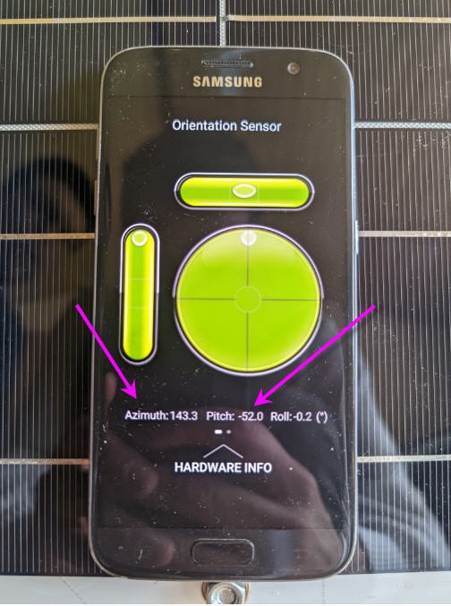
By the way, there are a lot of "sensors Applications" on the GooglePlay that you can use to precisely know the panel elevation and azimuth angle. Example "sensor box" for Android
Sitting your phone directly on the panel you can have the exact values for Azimuth and Elevation (complement to 90°)
![]()
-
MPPT Controller hardware
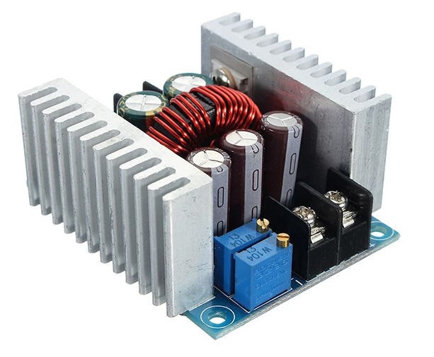
04/29/2022 at 16:46 • 8 comments![]()
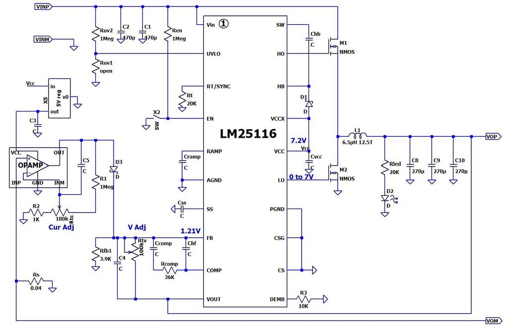
This cheap device follows this schematics (not sure that it is perfect but enough to understand the mod !)
![]()
You can control manually the output voltage with the multiturn potentiomer "V Adj". This is producing an offset voltage to the reference 1.21V. This offset is then taken into account by the LM25116 to correct the output Voltage (pin VOUT).
Another (more tricky to understand) voltage offset is issued on top of D3 and added to the Vadj one. This voltage is tuned by the CurAdj potentiometer which is acting on the feedback pin of an Op Amp, the positive pin being directly at the voltage of the shunt resistor Rs (thus proportionnal to current). So this Cur Adj offset is used to limit the current of the buck converter. Interestingly current control and voltage control share the same input on the LM25116 chip. Meaning that the LM25116 is only a voltage controlled device !
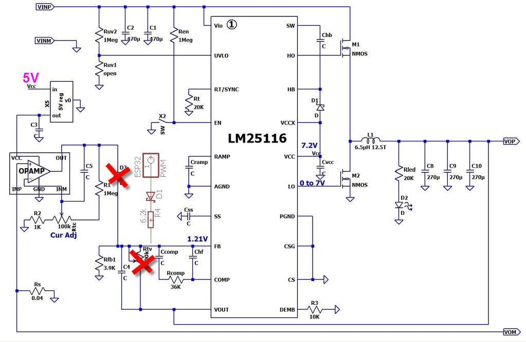
The hack consists in :
- removing the current Adj control (you can do it by desoldering D3)
- removing the V Adj potentiometer
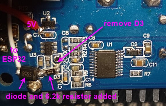
- adding a PWM voltage (seen as a variable DC voltage by the LM25116) in place of D3 and acting as a MCU controlled offset voltage. (So PWM + a 6.2k resistor + a diode)
![]()
No need to create a PCB for this... Soldering directly on the back of the Buck convertor is enough (quick and dirty ) !
![]()
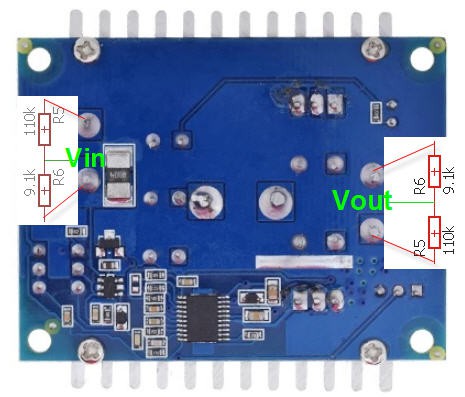
Similarly you need to measure the PV input voltage and the Buck Output voltage.
These signals will feed the ADC of ESP32.... so we need a voltage divider to bring all this down to max 3.3V...
![]()
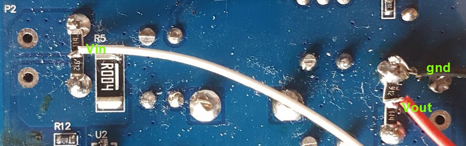
This simple schematics is also directly soldered on the back of the PCB... (quick and very dirty)
![]()
Now the only missing signal is the Solar panel Current.
I did try to reuse the Current sense OpAmp of the buck converter but I got more noise than proper signal...
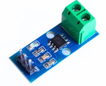
Finally I have invested a few more $ into a AS712 current sensor module. I selected the 20A version which is plenty enough for a solar panel with a 7A max output !
![]()
Once again no solder for this module but rather strong copper wires as all the juice is going through it....
This module needs 5V to be powered. Will be shared with the ESP32 5V input
Its output is a voltage between 0 and 5V but with a 0A output at midrange (2.5V). This means , as we only measure DC current, that (if properly wired) the output will only swing from 0 to 2.5V (0 for the max current of 20A). Just to say that there is no need for a voltage divider to accomodate 3.3V...
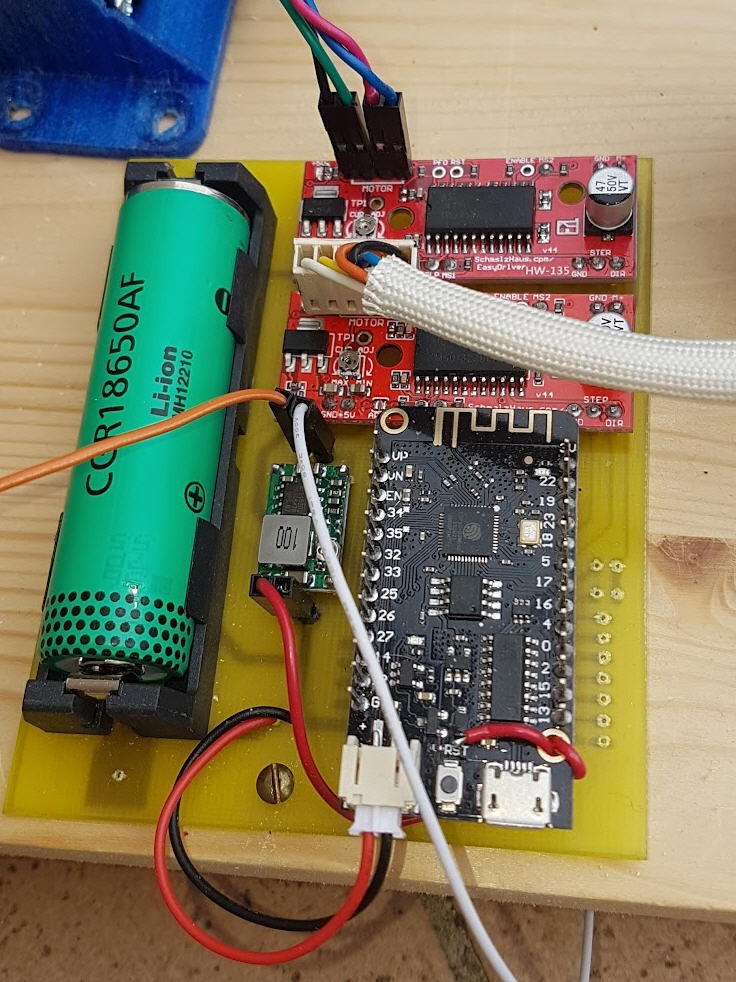
You will also need a small 360 DC/DC converter to step down the PV input voltage to 5V to power the ESP32 (the small 5V regulator from the Buck converter being to weak to power the ESP32)
And of course you will add another ESP32 lolin32 lite breadboard.
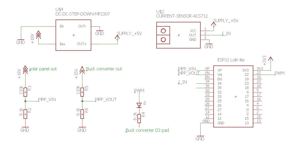
The overall schematics is quite simple : (one day I will do a PCB for this !)
![]()
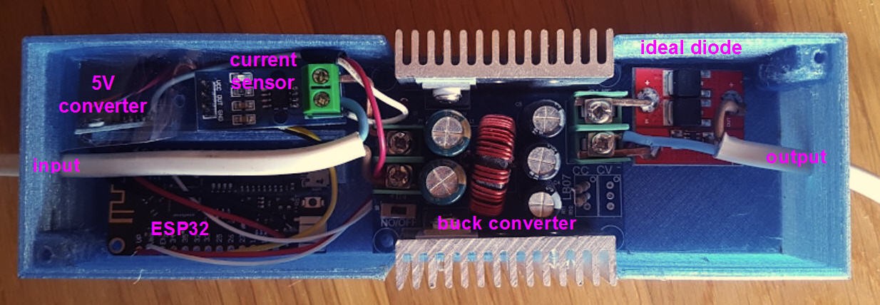
And finally to protect the output battery from reverse flow into the solar panel when no sun, you MUST add a strong Schottky diode on the positive Vout pin. If you have a few $ to spend (I had) then a good choice would be to replace this diode by an ideal diode. It is the red module on the output of the Buck converter picture
The final integration is depicted on this photo.
![]()
-
Solar Tracker electronics
04/28/2022 at 19:03 • 0 commentsThe electronics part of the solar tracker is quite simple as we reuse existing components which are mostly only integrated all together on a custom PCB.
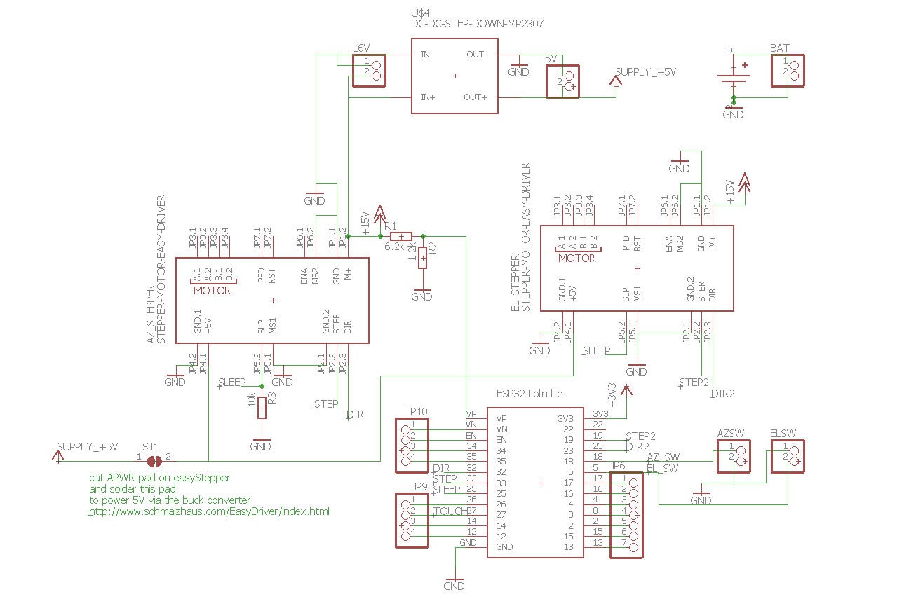
Here is the schematics :
![]()
The heart of the system is the Lolin32 ESP32 breadboard.
It is driving two steppers motors via two easydrivers boards. These drivers accept classical Step and Dir signals.
They can be switched into "sleep" mode preventing to draw too much current when the motion is finished. Note that in Sleep mode, the motors will loose their torque and may rotate freely.
Thanks to the "wormgear" design of the mechanical parts, the axis will not move if a force is applied on the panel even when the motors are off.
The board is powered either directly from the solar panel or via an external battery (which will be charged by the MPPT controller).
Nevertheless it may occur that the voltage at the input of the motors is not enough to perform a strong motion. This is the reason why this voltage is measured via the voltage divider R1/R2 and the ADC input of the ESP32 (VP pin).
Note as well that the lolin32 is equiped with a lipo charging circuit. This is why I have added a single cell 18650 li-ion to the board. This will allow to power only the MCU if the 16V signal is weak or not present. Doing this allows to preserve the software side of the system and thus to recover from cloudy situations !
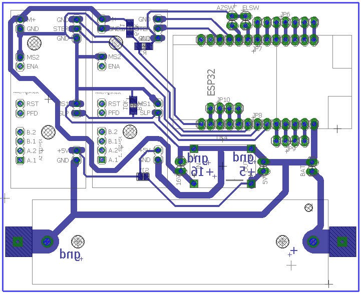
This schematics has been translated into a single sided PCB
![]()
The PCB itself was etched with my "toner transfer" method explained on my web site.
![]()
Refer to the Gerber files log if you want to manufacture your pcb.
-
Solar Tracker mechanics
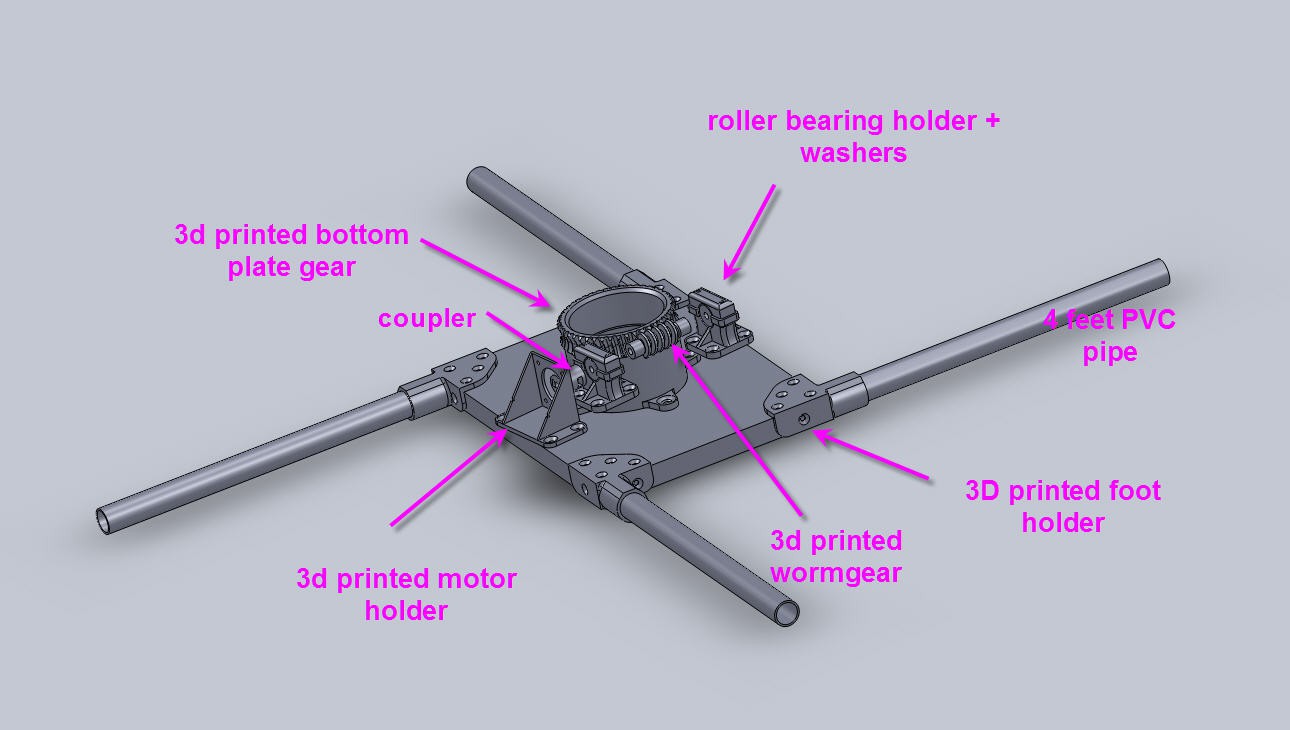
04/28/2022 at 16:57 • 0 commentsAzimuth axis
![]()
On this CAD picture only the bottom plate is shown.
Between top and bottom plate is inserted a lazy Susan turntable bearing.
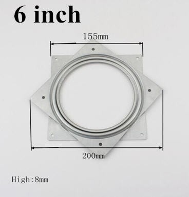
![]()
Be sure to choose a 6 inch model . The main gear must be able to enter the hole of the lazy Susan.
It must also be perfectly centrered with the Lazy Susan center. Be careful.
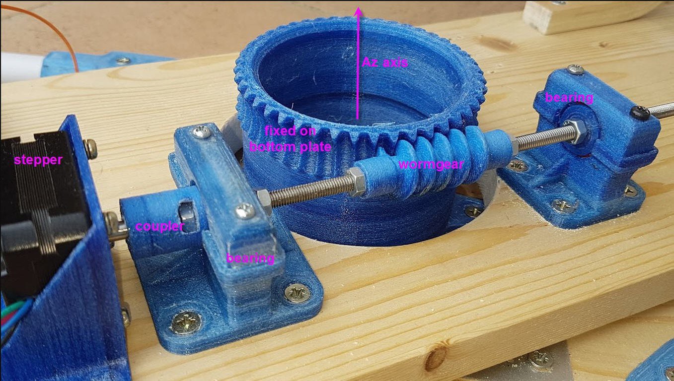
Here is a view of this axis finished :
![]()
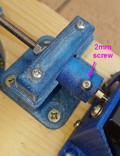
The coupler must be fited with a 5 mm screw (visible on the top picture) and a 2mm one on the other side
![]()
Align everything and screw the bearings holders in place. Lock any motion of the wormgear with 5mm nuts.
Do the same for the elevation axis :
![]()
All the 3D printed "hinges" must rotate freely on their respective axis. FIle the parts to achieve this !
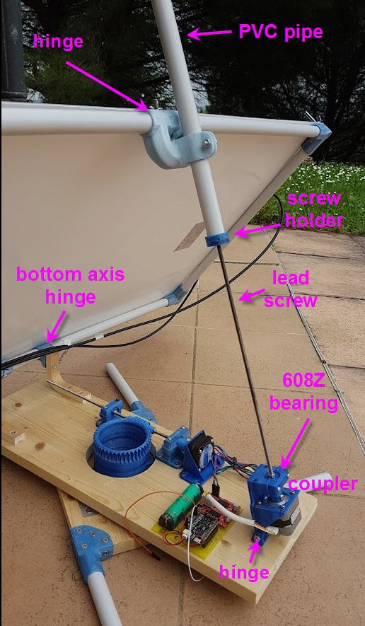
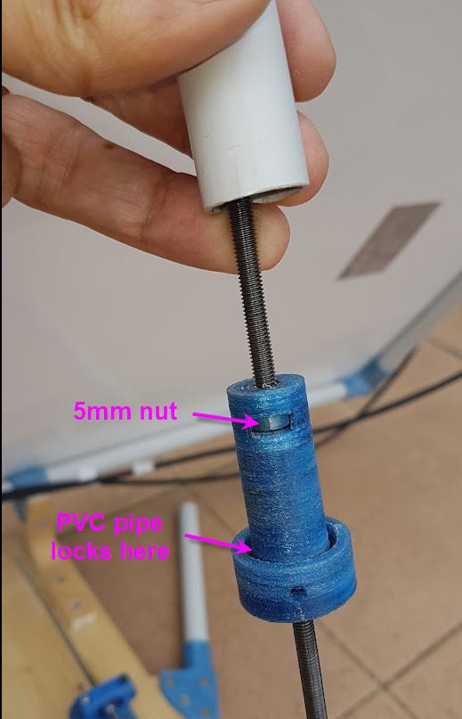
Here is a detailled view of the "screw holder"
![]()
This is the part which achieves the translation of the linear actuator of the Elevation axis. As it is fixed to the PVC pipe which is also fixed to the top hinge of the frame, when the lead screw rotates then this part can only go up or down, pushing or pulling the top of the frame !
As visible on the picture (black dirty color), you should add a few drops of oil on the leadscrew to ease rotation.
-
frame finished
04/28/2022 at 11:08 • 0 commentsframe description is now finished !
It was an easy section !
Low cost solar panel solution (MPPT + sun tracker)
portable flexible panel + MPPT controller + solar tracker system less than 55 USD ????