 Open Green Energy
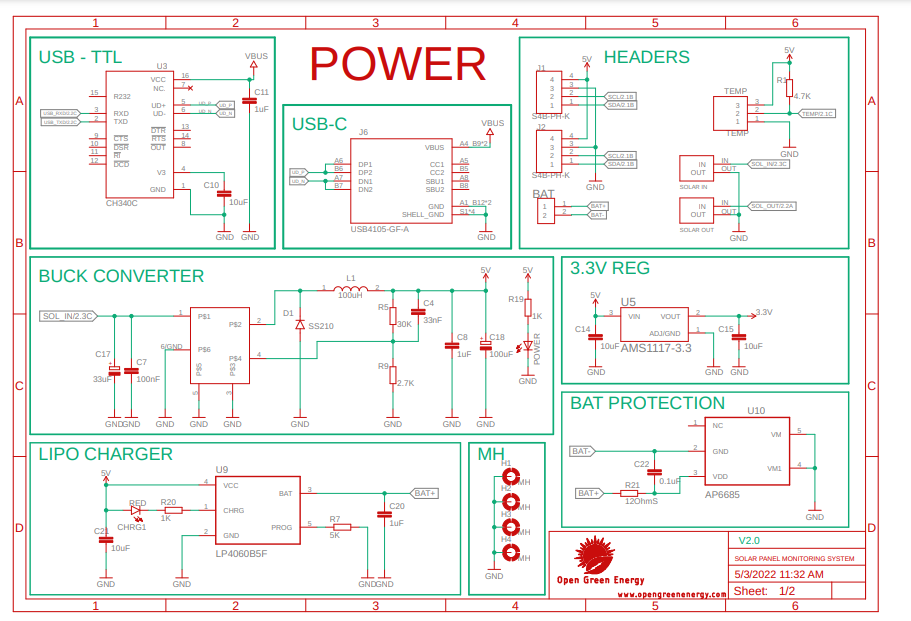
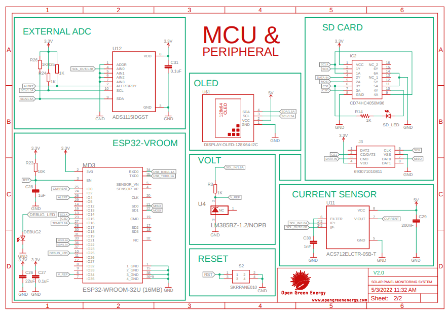
I have drawn a new schematic with the following new features
1. Replaced the ESP32 development board with onboard ESP32 WROOM-32 to reduce the power consumption. Also added the USB programming interface.
2. Replaced the XL7015 module by using an onboard buck converter for the power supply
3. Added battery charging circuit for using a Li-ion battery as backup
4. Added two new I2C ports for using additional sensors
5. Added SD card slot for storing the data for analysis
6. Added an external ADC ( ADS1115 ) for accurate analog readings
7. Added a voltage reference IC for getting a stable voltage reference for calibration of sensor readings
Discussions
Become a Hackaday.io Member
Create an account to leave a comment. Already have an account? Log In.