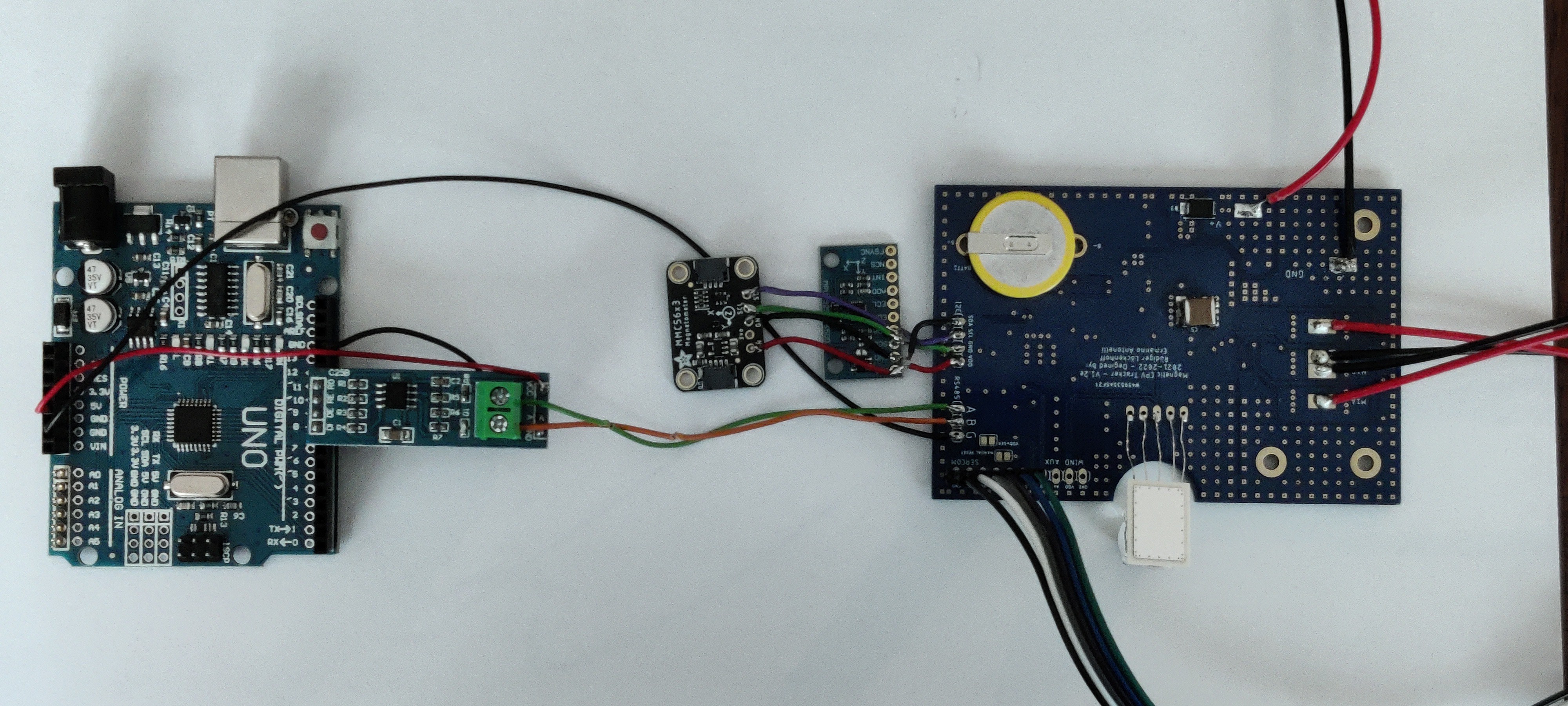
This is a contest and you deserve that I show you all that we have.

It doesn't look like much and that's the whole idea. To the right you can see the tracker control board with the sun sensor at the bottom. The motor cables extend to the right and the 24V supply to the top. In the center of the picture there are two breakout boards that should not be there. One is the old MPU9250 and the other an MMC5603 magnetic compass. The problem was that the MMC5603 magnetometer and the MXC4005 accelerometer are sub millimeter in size and just not hand-solderable. So presently I am using the old MPU9250 tilt sensor and the MMC5603 magnetometer. In a few days I will also receive the MXC4005 breakout board and I will connect it in parallel to the other breakouts for testing. Once this is done, Ermanno can finalize the board and we will have it made by our sponsor PCBWay. By then, the small breakout boards will be gone and we will have a couple of final boards.
They are meant for testing by anyone who is interested and who can make us believe that he/she has a real project in mind.
To the left you will probably recognize an Arduino Uno with a MAX485 breakout board. Yesterday I successfully demonstrated a half duplex communication between the boards. We wont have the final board at the end of the contest but shortly after - I promise.
As you can see the board will be approx. the size of an Arduino Uno and capable of controlling up to 50V, 8A = 400W. That's enough for a 100 square meter solar tracker - if you absolutely wanted to go big. I demonstrated a tracking precision much better than 0.1° in an earlier project log.
 Ruediger F. Loeckenhoff
Discussions
Become a Hackaday.io Member
Create an account to leave a comment. Already have an account? Log In.