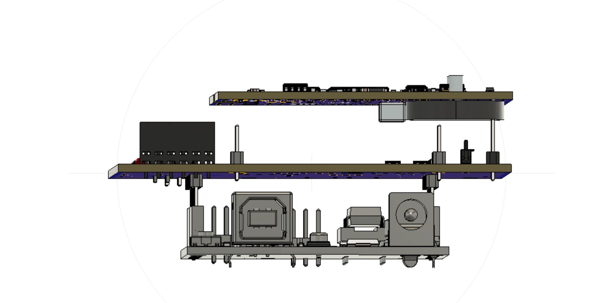
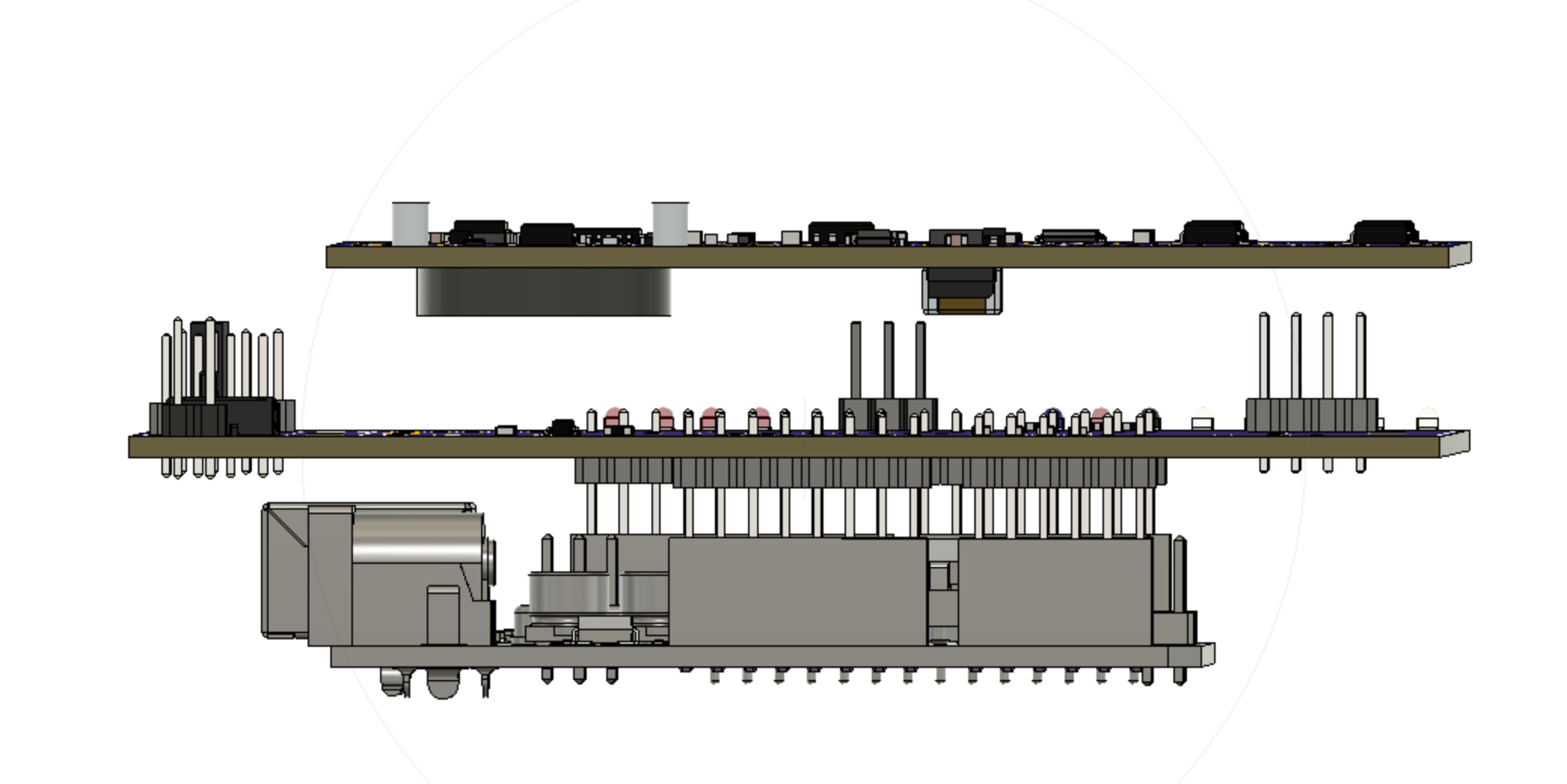
After several discussions with Ermanno he finished the design of the test board with pogo pins that will serve for ICSP programming and testing of all components of the tracker board. In the figure below you can see the test board in the middle. It is mounted as a shield on top of an Arduino Uno and the tracker board is pushed backside down onto pogo pins (pogo pins not shown). The Arduino UNO can either serve as an ISCP programmer or as a test platform.


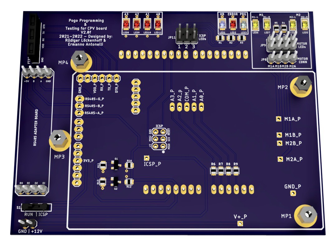
And here is a rendering of the populated tracker board.

The positions that will get pogo pins are marked with a _P in the silk screen. The RS485 adapter will be on the left with the voltage selection switch (Run / ICSP) underneath. The four LEDs on the upper left side should only come on when there is something wrong with the sun sensor. They are a protection for the tracker board when we are applying 5V through a resistor to test the analog input.
Then there are the ICSP status LEDs on the upper right. Finally the motor output with status LEDs is in the upper right corner. The tracker board is pused onto 3mm screws and fixed with nuts to make it push down against the pogo pins.
A full test will probably include the following steps:
1) Upload bootloader and test program via ICSP.
2) Change voltage to 3.3V and power up all 3.3V hardware by swapping a switch. Connect 12V supply.
3) Run a test programm to check compass chips, RTC, photodiode tracking sensor, motor controll (all directions), motor current measurement, RS485 communication between tracker board and UNO.
4) Calibrate z axis of the accelerometer by swapping the assembly upside down. Store the results in the EEPROM.
5) Use FTDI adapter to upload the tracker program and check that the bootloader is working.
With these steps, the tracker is ready for shipping. Since we must reprogram the UNO between 1) and 2), we will probably do 1) for a couple of boards and go on with 3)-5). We will need some of those QC stickers too, to make it look professional.
Ermanno will upload the board to PCBWay and we will see whether it processes correctly. I will order a few boards then to build up at least two test rigs.
As soon as PCBWay confirms that the CAM files processed correctly, we will upload them here as open source (MIT license).
 Ruediger F. Loeckenhoff
Discussions
Become a Hackaday.io Member
Create an account to leave a comment. Already have an account? Log In.