The idea for this project came from a brainstorming session with my friend Jerry. We were trying to come up with a good application for circular TFT LCD displays. Meters of course came to mind, there was a time when they were usually circular. Then it occurred to me that these displays were small enough to fit into the very limited vertical space of a 1U rack box. And with these one could create a meter array like on old mixing consoles.
Console meters are normally rectangular, and the same idea would have worked with rectangular screens...but whatever. How the mind works, nobody knows.
So we ordered some of the displays, and got to work on a board for mounting them. Jerry helped me to create the board in Kicad. I have been an Eagle user, soon to change over to Kicad. The dimensions were too big for my free Eagle license, and my paid-for Eagle license disappeared when that software changed ownership.
The board is largely just a means of mounting the screens. It has a few connectors on it, and a 74HC138 which enables the MCU to select a display, but requiring fewer signal lines. The MCU outputs the number of the display (0-7) then proceeds as it would normally if talking to only one display.
I chose the Teensy 4.0 because for its high throughput, as I imagined driving multiple displays might require that in the worst case. With this simple meter, its just line drawing, and line erasing, which most likely could be done with a less capable chip.
The Teensy is mounted on a breakout board that I created earlier. Its part of a set of boards I made for prototyping rack mount systems. Its mostly just an MCU socket broken out to some connectors. The serial ports interface at 5 volts, because that was what MIDI and DMX needed. So its got some level shifters on it. I also had the SPI port brought out at 3.3V on a 2x3 header with same pinout as the Atmel ICSP (Arduino programming port). That is used for writing the displays, though I messed up the pinout on one of the boards, and so used Dupont jumper wires to connect, rather than a ribbon cable as intended.
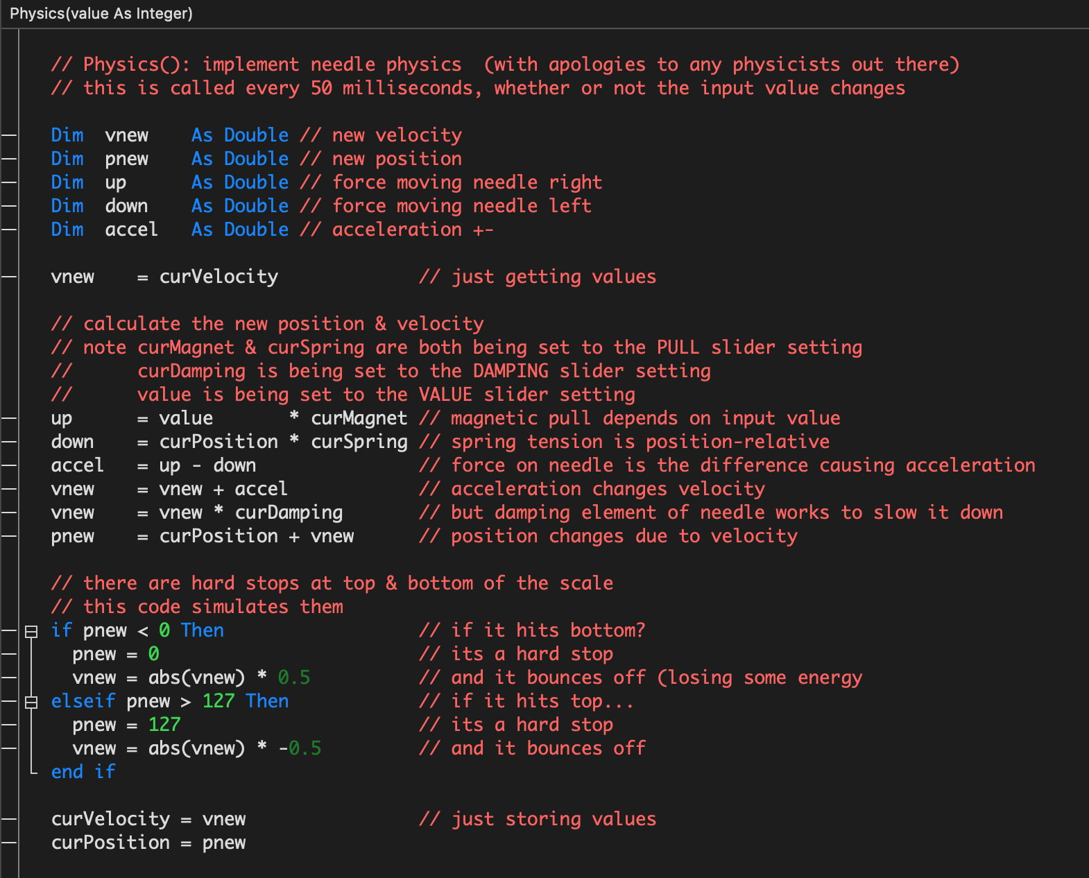
The Arduino code utilizes the PNG decoding library from Larry Bank. Also it uses code from https://github.com/moononournation. The needle drawing and GC9A01 driver were adapted from his code.
 Tom Dowad


Hi Tom, those gauges look neat. Any chance you'd share the final code? I'd like to reuse it in ESP32-audio projects