Here are some of the most important key facts:
- Compact design: Total size 120 x 50 mm. Approx. 70.5 x 50 mm area for electronics and additional 49.5 x 50 mm to mount a scintillator.
- All-in-one: No external parts (e.g. sound card) required to record gamma spectra.
- Standalone spectra recordings on built-in flash.
- Easily programmable using drag-and-drop firmware files or the standard Arduino IDE.
- Low-voltage device: No HV needed like with photomultiplier tubes.
- Can use SiPMs in the voltage range of 27.5 V to 33.8 V.
- 4096 ADC channels with built-in 3 V voltage reference.
- Energy resolution of up to 7% @ 662 keV possible; highly dependent on your SiPM/scintillator assembly.
- Energy Mode: ~10 µs total dead time while measuring energy (default settings).
- Geiger Mode: ~1 µs total dead time without energy measurements (default settings).
- Low power consumption: ~15 mA @ 5 V with default firmware at normal background.
- Built-in ticker (buzzer) for audible pulse count rate output.
- Additional broken-out power pins and I2C, SPI and UART headers for custom parts (e.g. display, µSD card, etc.).
- Simple OLED support out of the box (SSD1306 and SH110x).
- Built-in True Random Number Generator.
More information can also be found in the GitHub repository...
Ok nice, but how do I get it?
- DIY version: Download BOM and Gerber files or use Kitspace.
- Buy a complete board: Head over to Tindie.
- If you don't want to deal with all of that, feel free to contact me. Just send me an e-mail if you want and we'll figure something out.
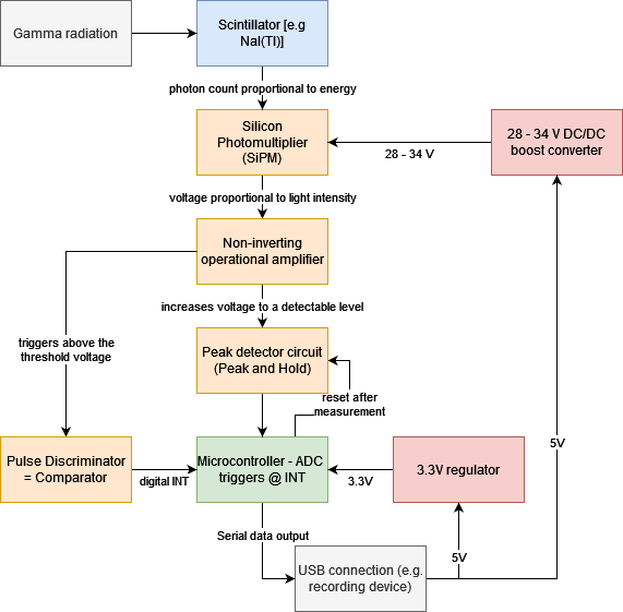
The principle of operation for the detector looks like this:
The PCB has four layers and components only on the top layer so that it is relatively easy & cheap to manufacture and assemble by hand. I also chose to use mostly 0603 size components where possible that can still be hand-soldered with some practice, but make PCB layouting much better and the whole device more compact. This is what the PCB front side looks like:
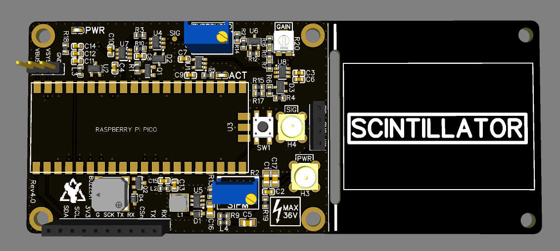
Connection between the detector board and SiPM can be done via some short cables directly to the pin header on the right side or special MCX connectors that are more reliable. You can then lay the whole SiPM/scintillator assembly onto the PCB and secure it with cable ties. If you don't need the extra space you can cut off the PCB at the white lines. There is already a board cutout to help with cutting.
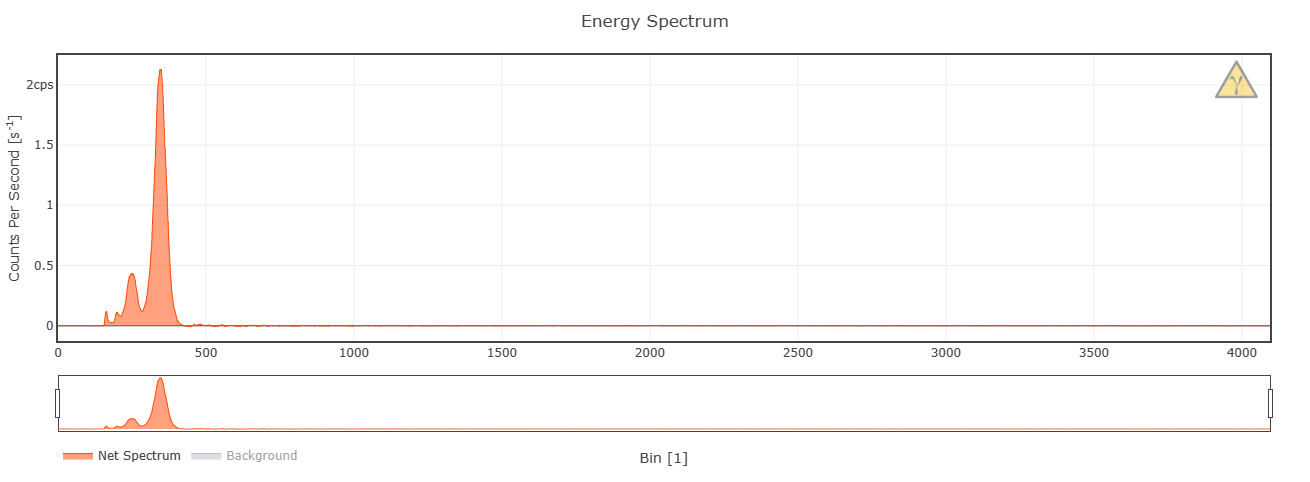
Depending on the scintillator size (which changes the amount of photons emitted), desired energy range and resolution, you'll need to change the discriminator threshold voltage. This will ideally only be done once, since you probably don't switch scintillators on a daily basis. I'm using a 30.5 cm^3 scintillator for all of the measurements below.
To analyze the recorded spectra and plot the serial data live, I have set up a progressive web app. With it you can download and export spectrum files, connect via the serial interface straight to the Pico and much more!
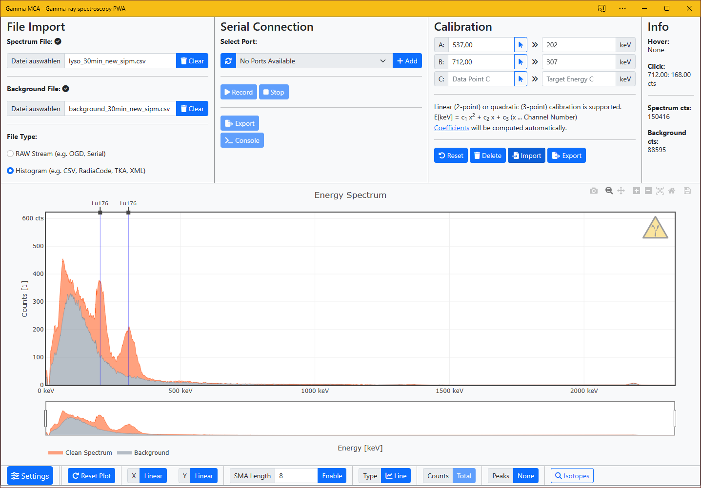
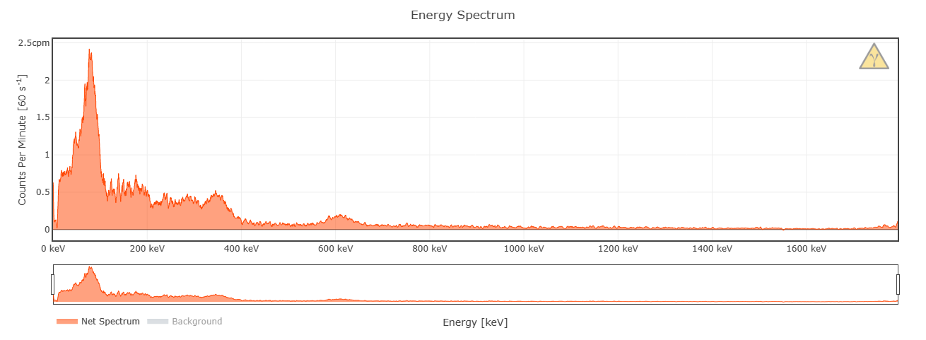
Some example spectra:
 NuclearPhoenix