Hi there!
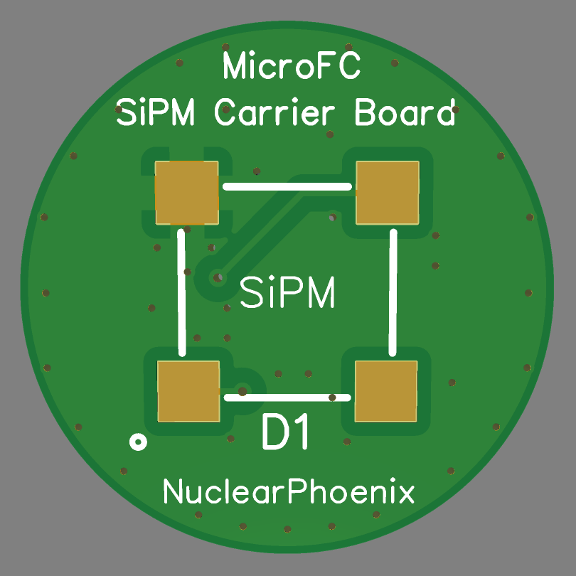
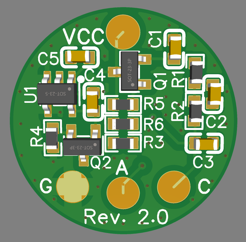
Here is a new and updated revision of the MicroFC SiPM carrier board: It now has some extra circuitry for temperature gain compensation! The overall size of the PCB and the solder pads have not changed at all and the bias filtering is also still on there. In addition to that, you can also use it without any of the additional electronics on it too. Don't need temperature compensation or any of the filtering? Just leave out all the components on the back side and solder directly to the anode and cathode pads for the SiPM.
If you do want to use the compensation circuit, a new BOM, Gerber file and schematic have been uploaded to GitHub. Kitspace should update too in the next couple of days (hopefully). Here is a link to the repo: https://github.com/OpenGammaProject/MicroFC-SiPM-Carrier-Board
It works completely passively without any sort of user intervention. It's based on an NTC thermistor that sits on the back side of the PCB, which is a big plus for temperature accuracy since it's on the same board as the SiPM. It's also low-power enough so that there is no unnecessary self-heating of the PCB. Just be sure to increase the SiPM PSU voltage a little bit as the compensation circuit initially drops a couple of 100mV to increase the temperature range without any need for readjustment. And ideally, you'd want to set the correct voltage at around normal ambient temperature for the correct tracking range (e.g. ~29.5V @ 25C).
Most of the research and testing has been done by Sebastian D'Hyon, so big thanks to him.
Finally, here are some screenshots on what the new board looks like:


Cheers!
 NuclearPhoenix
Discussions
Become a Hackaday.io Member
Create an account to leave a comment. Already have an account? Log In.