The latest hardware revision of the board is now almost complete. I've finished work on the hardware, did some testing and adapted the Arduino sketch to work on the new hardware just now. I'm very shortly going to talk about all the changes with the Rev 4 hardware.
Most of the actual circuitry has been taken straight from the last revision with only minimal changes. So like I said in one of the last logs here on Hackaday, this is mostly a quality of life update and largely concerning the change of the PCB layout.
Here is a list of all significant changes to the electronics:
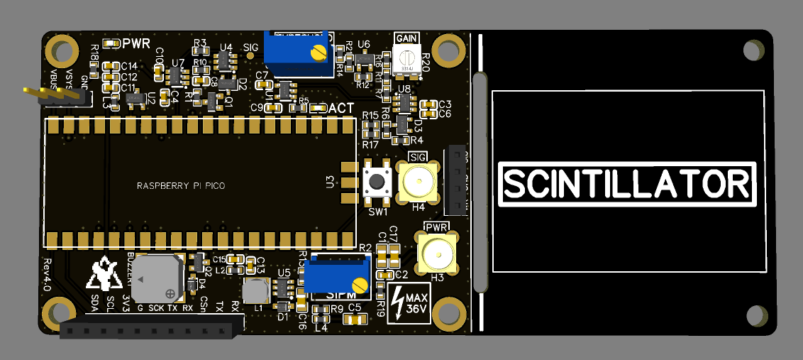
- Added a small buzzer
- Added an additional button
- Added two MCX connectors for a much improved and reliable connection to your SiPM/scintillators
- Added an optional gain trim pot for the pre-amp
- The PCB now has 4 layers instead of 2, with much improved board layout and layer stackup resulting in a lot less noise according to my tests
- Changed the two 4-pin and single 2-pin headers for a single 10-pin header for the broken-out GPIO pins
- Added an additional cap to the SiPM PSU output for better stability
- Increased decoupling cap size in general all over the board
- Swapped out some critical resistors for ones with less tolerance and a much lower temperature dependency to increase the detector response over vastly different temperatures. In the past especially the threshold voltage could be easily disturbed by a change in temperature. This is now a lot better according to my testing as well, I didn't have much of a threshold drift up to almost 60°C.
- Decreased the threshold voltage range maximum to a more reasonable value. This also makes setting the right voltage a lot easier and helps with drift.
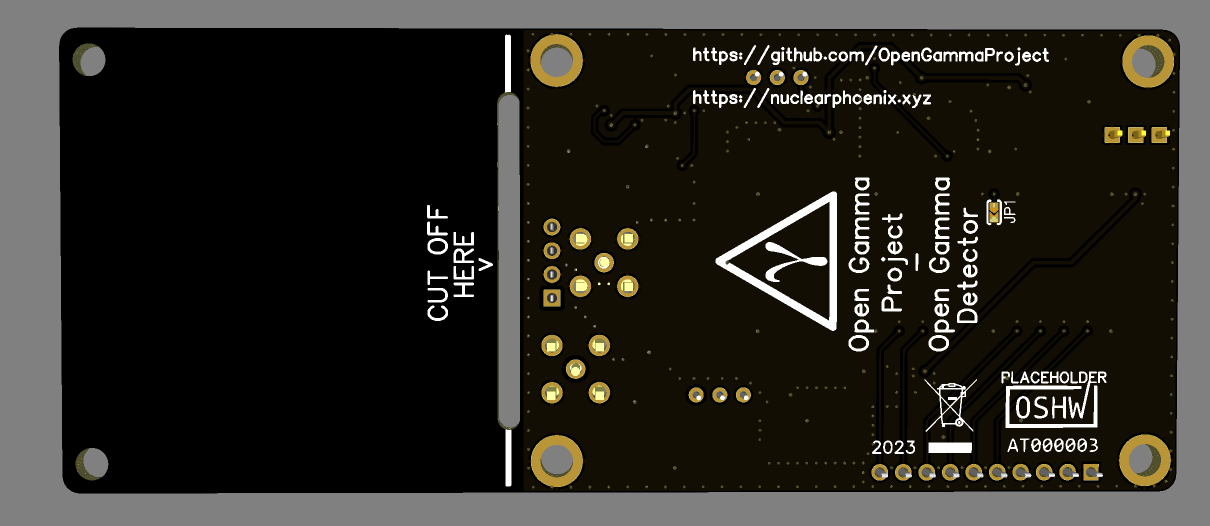
- Added a board cutout to help with separating the two PCB sections if you decide to cut the additional space off
- Some part consolidation (BOM)
Admittedly, this is all a bit technical, but I guess you're here for the tinkering and the behind-the-scenes stuff anyways ;D
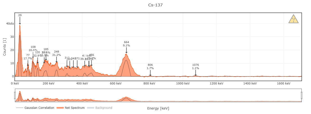
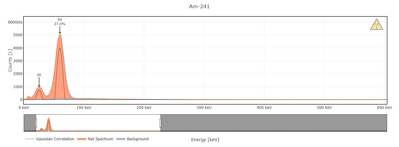
In short, what does this mean for you, the user? Well, first of all, you finally got a buzzer and an additional button, how nice is that? You also got a more reliable option to connect the SiPM if you so desire. The device should also be a bit more stable now in general. And on top of all of that, I got a noticeable improvement in energy resolution (up to 1%, but I have to do some more testing on that) and I was even able to get a usable spectrum down to about 10 keV due to the less noise!
Here are two test spectra that I did that back what I just told you (only 30 minutes, so expect results to be a bit better with longer recordings):


Here are some renderings on how the final PCB looks like (with an OSHWA mark placeholder). I already have an assembled one here, but that's nothing worthy of showing off due to all the soldering and changes I did to it ;)


I am going to do some more testing for the Arduino sketch that runs on the Pico and I still have to implement the button and some other buzzer-related things. It already works totally fine and stable just like the old software, only some functions are missing and I want to do some more optimizations on top of that.
There will also be another batch of assembled PCBs on Tindie in a couple of weeks, this time the pin female headers on the board will also come pre-assembled in contrast to the last batch where they were left out. Price will probably need to go up like $5 per piece to compensate for the added parts and the 4L board, but I think that's more than fair given the number of improvements ;)
So stay tuned for more updates on the Tindie stock as well!
In addition to all of that, the PCB will also get a final, tiny update when I get the OSHWA certification again (just adding the mark to the silkscreen). There is still a lot to do for me, I'm going to slowly update everything here on Hackaday and on GitHub over the next few weeks, I will keep you updated.
Have a nice week!
 NuclearPhoenix
Discussions
Become a Hackaday.io Member
Create an account to leave a comment. Already have an account? Log In.