 Open Green Energy
I have designed a new PCB as per the schematic V2.0. There are two different PCBs
1. Main Board
2. LED Board
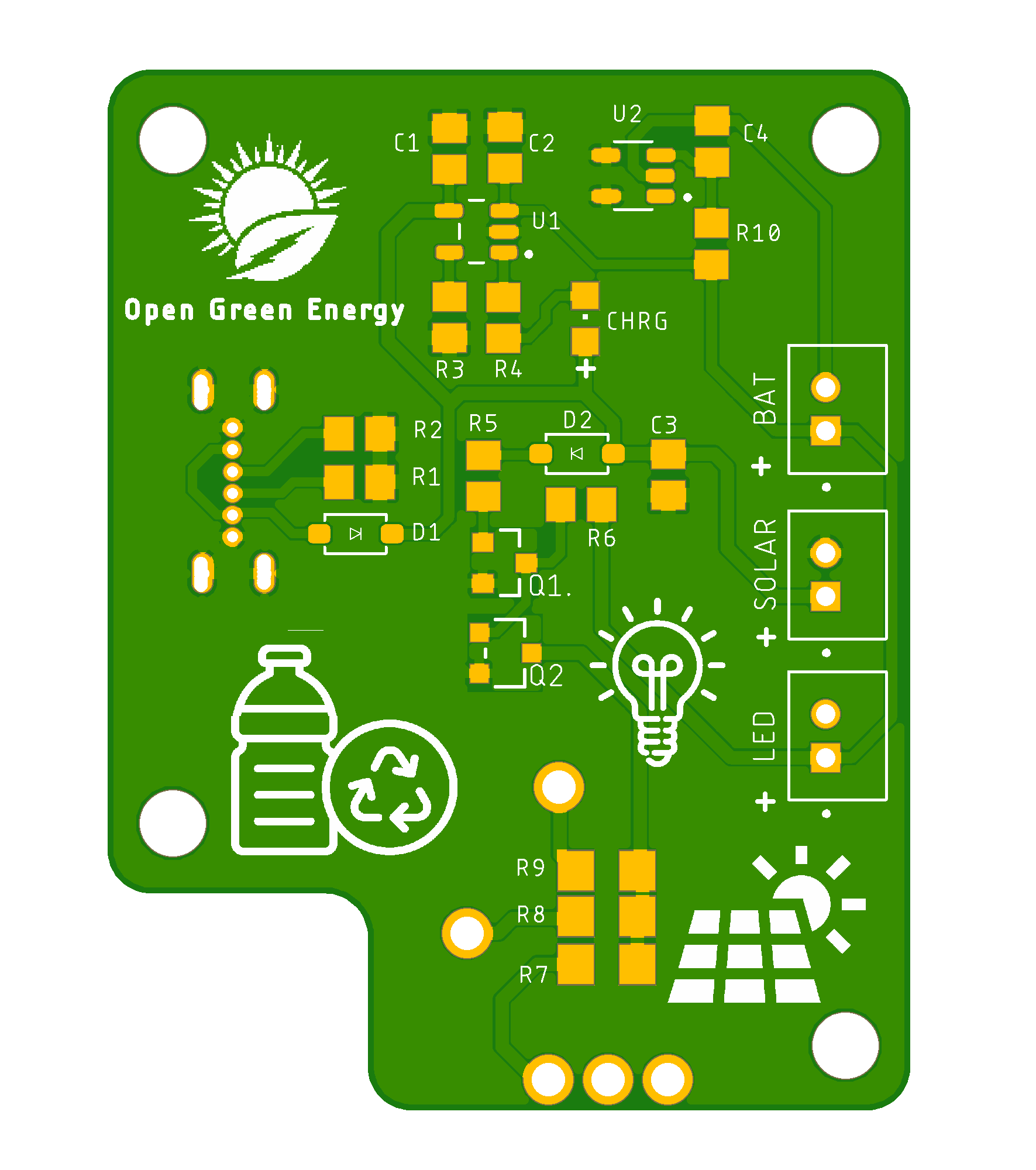
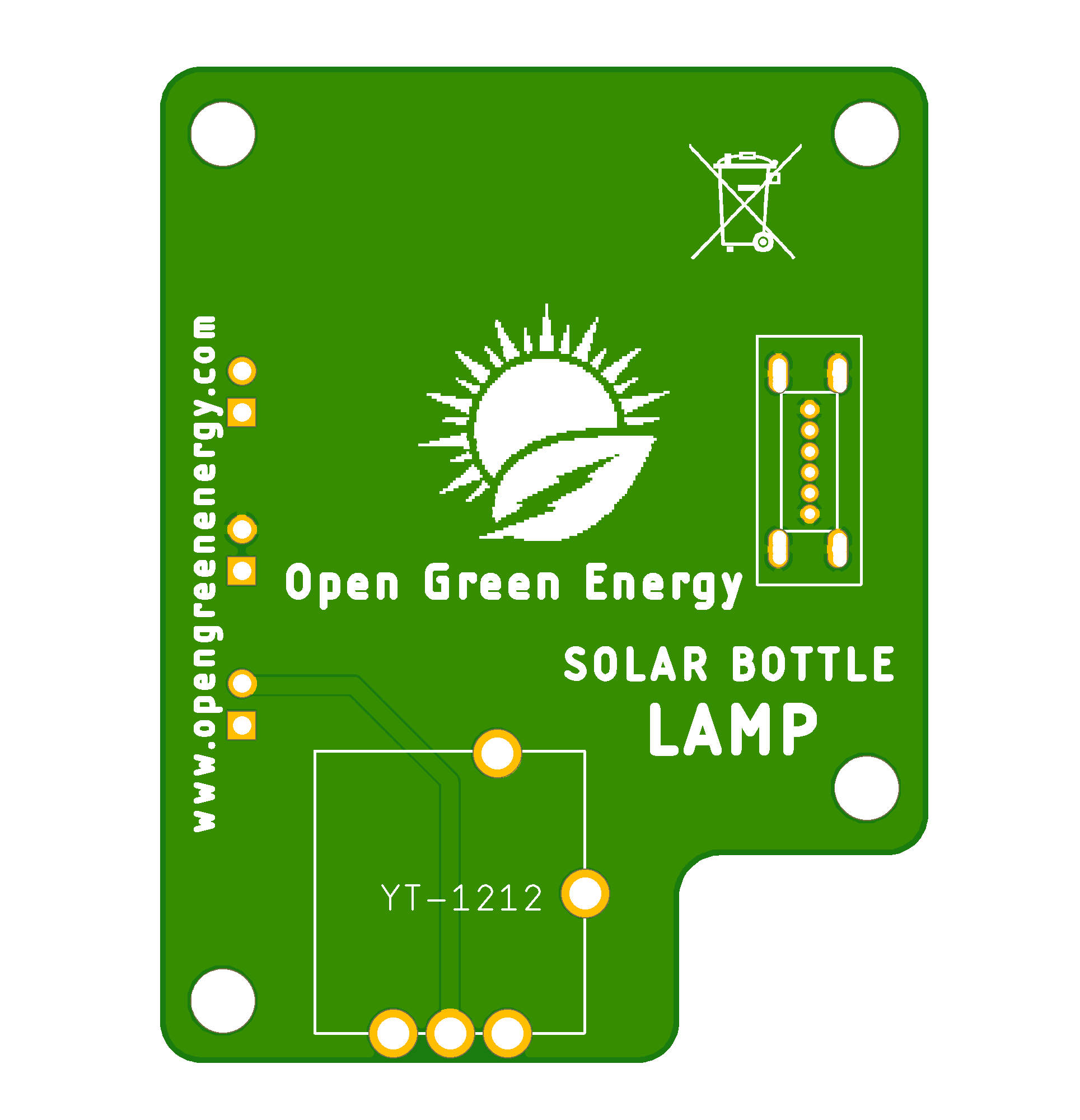
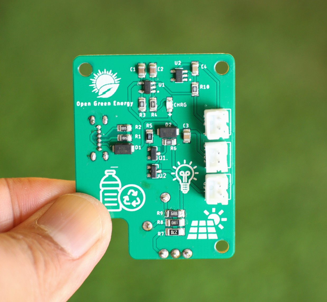
Main PCB Board:
The main PCB includes all the circuits for charging the battery, LED driver, and battery protection. I have used all the SMD components with the 0805 packages ( except the LED current limiting resistors R7, R8, and R9 which are 1206 packages) so that they can easily be hand soldered.
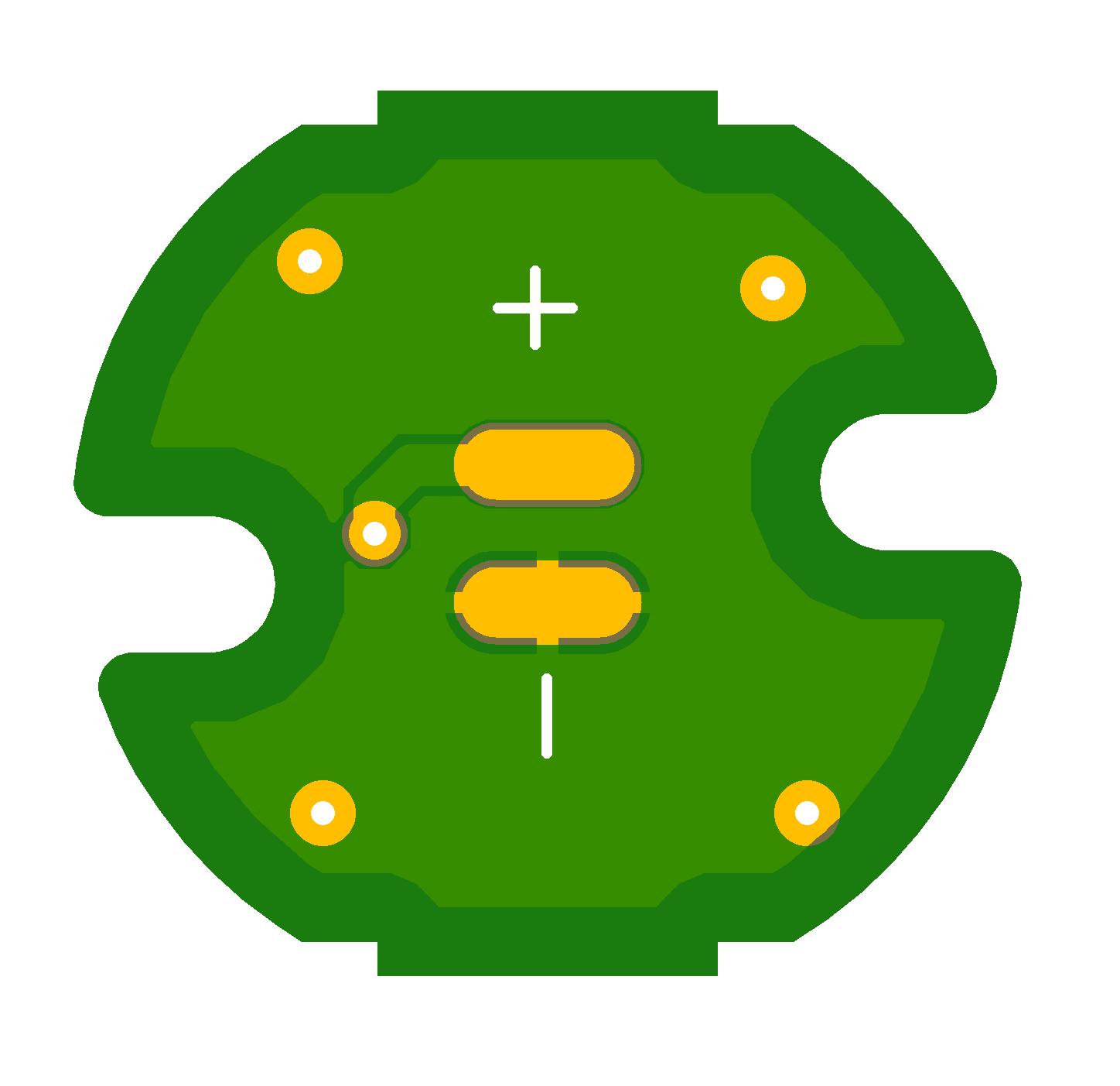
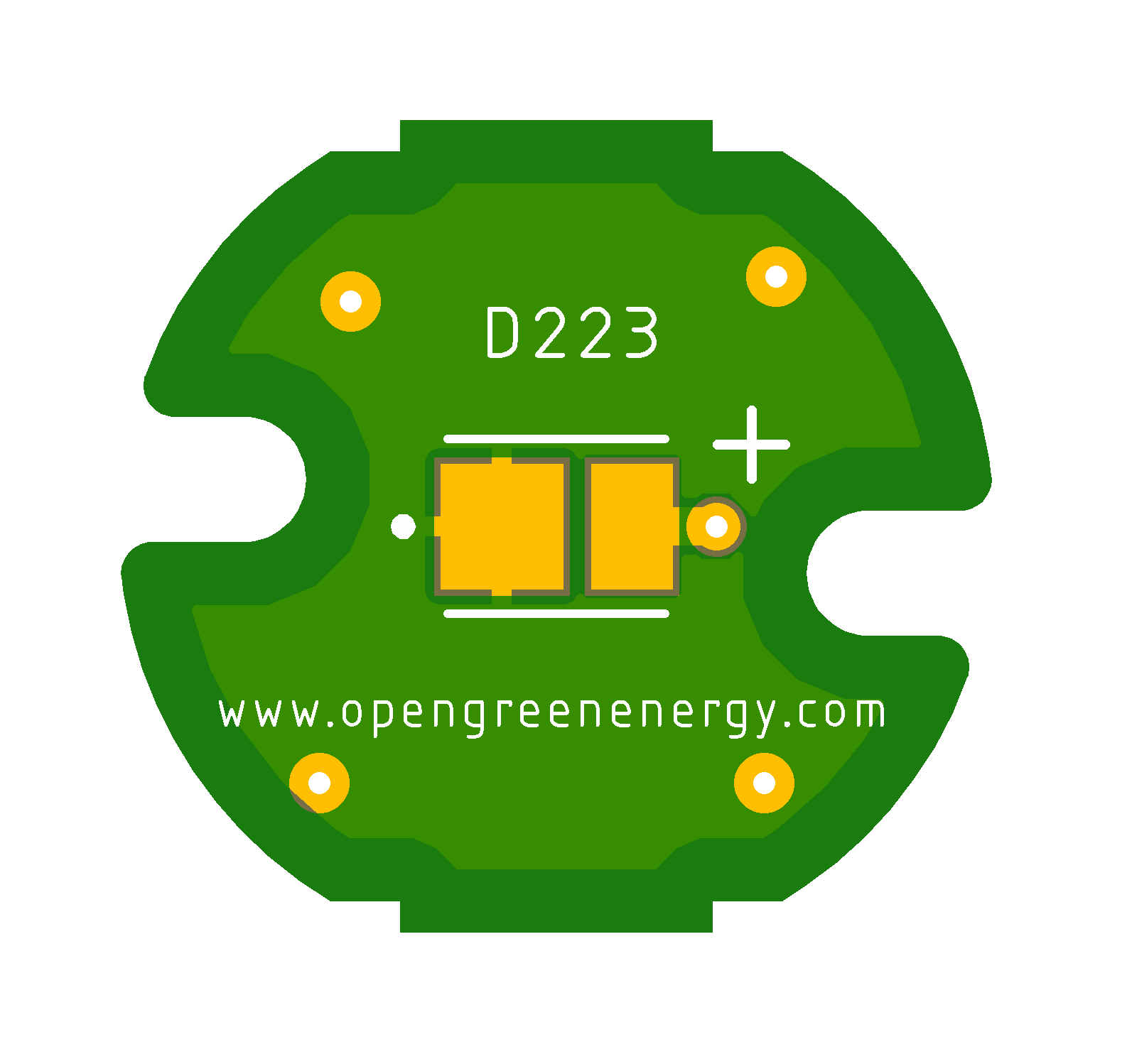
LED PCB Board:
The LED PCB board only uses the 0.5W SMD LED ( 2835 package ).
Update 02.08.2022
PCB Arrived :
I ordered the PCB from PCBWay, the PCB arrived within 7 days. The PCB quality is really awesome.
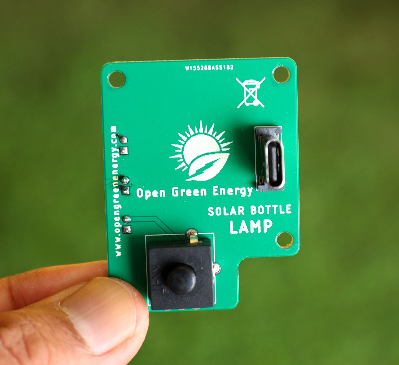
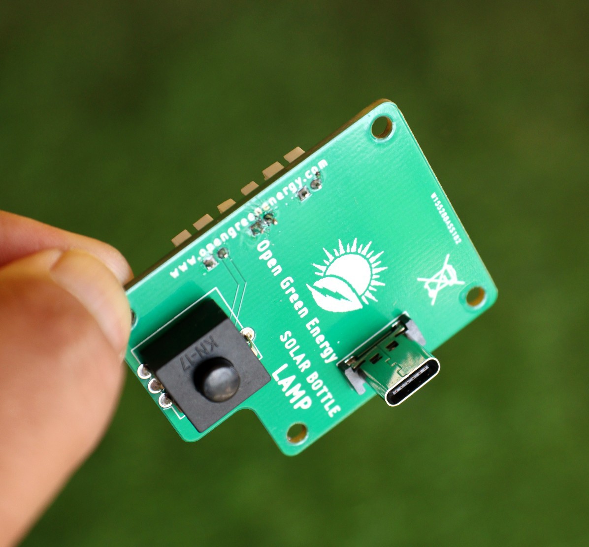
Following are the images of assembled PCB.
Discussions
Become a Hackaday.io Member
Create an account to leave a comment. Already have an account? Log In.