 Sean Billups
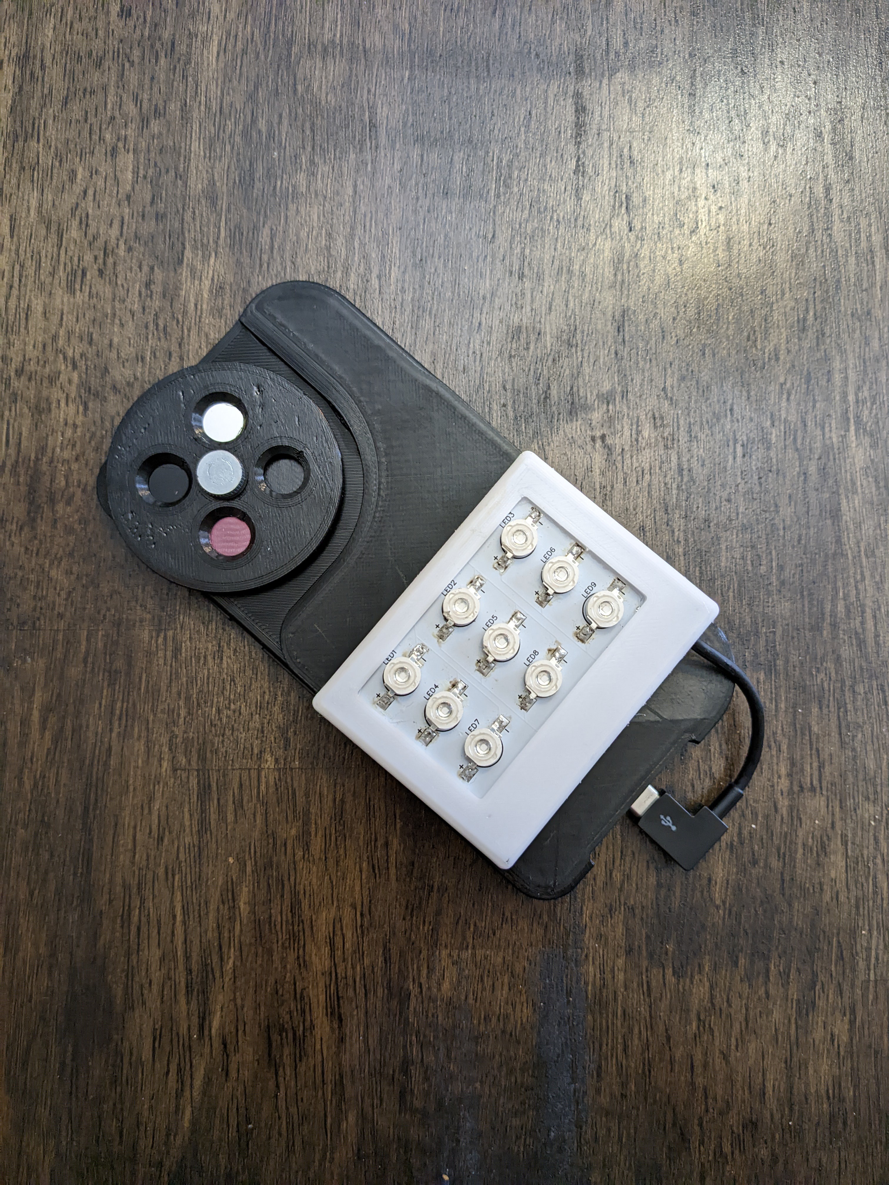
I made a PCB for prototyping the LED modules. This is my first PCB, so it's very simple, but the through hole points allow for soldering in header pins & testing various configurations of resistors/potentiometers/switches, etc.
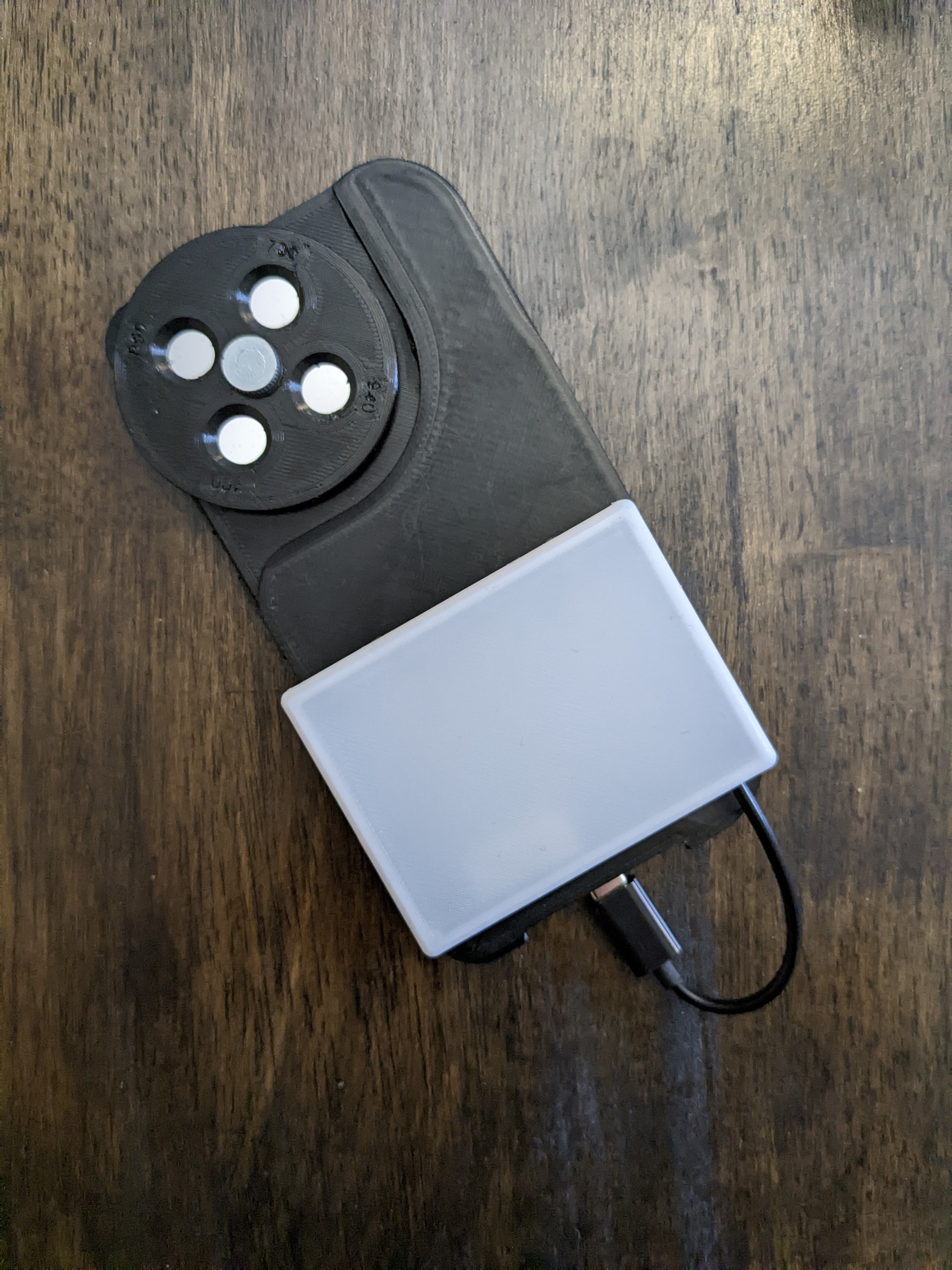
I used a few USB-C OTG cables to wire up to the PCB, cutting out the data wires.
First, the IR module: I made the 850nm module first, since that is the wavelength of bandpass filter that has been the most consistently useful in my tests. The PCB has an array of 9 LEDs in a grid, which has given enough output for photos up to 5-6 feet away from the surface.
Next, the UV module, which needed to be mounted on top, without the diffuser over it, because the shorter UV wavelengths won't go through the diffuser.
Discussions
Become a Hackaday.io Member
Create an account to leave a comment. Already have an account? Log In.