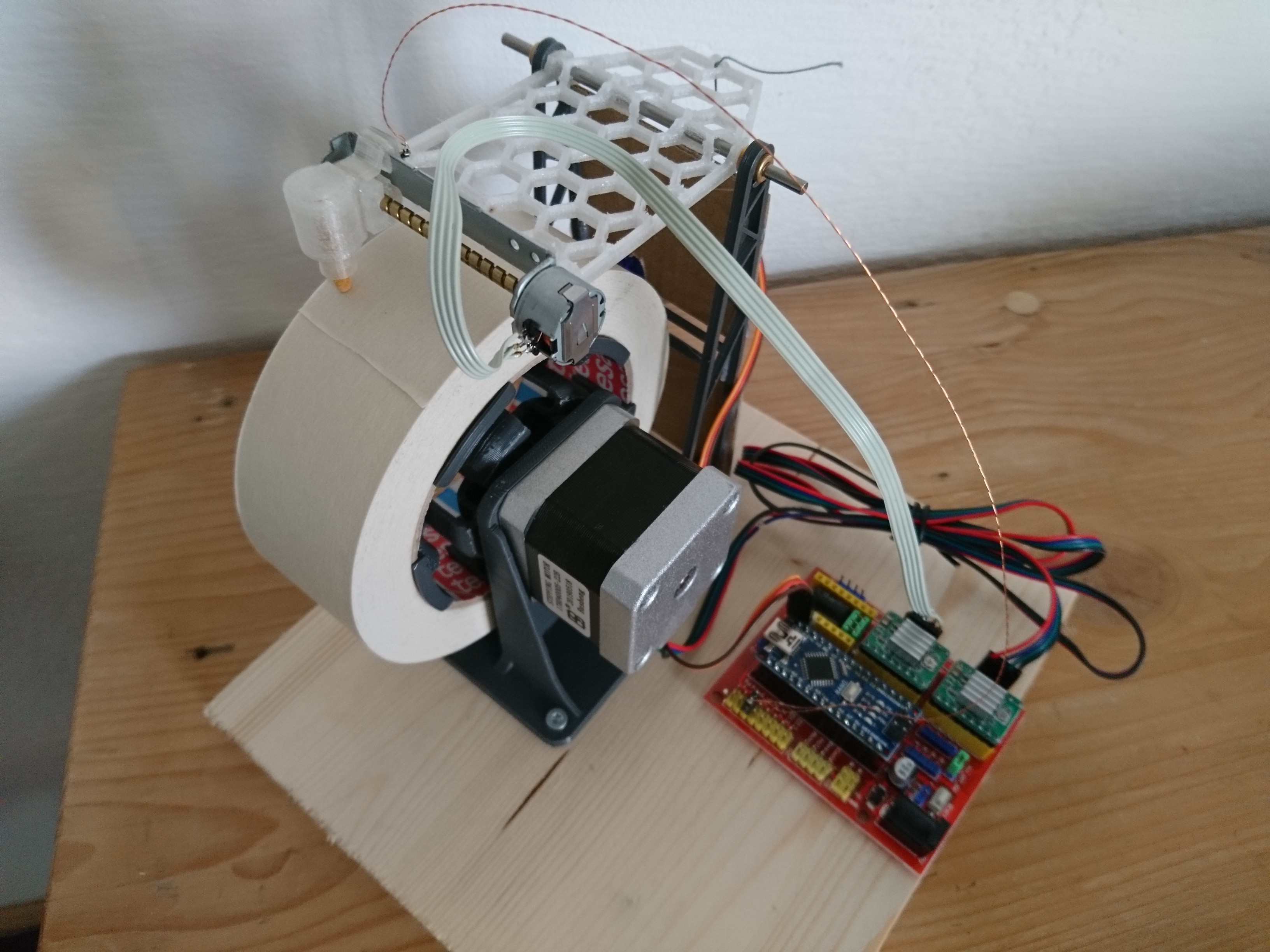
I built essentially a drum plotter, but one that uses masking tape rolls as the drum. The hardest part was to construct a z-axis that had almost no friction so the pen could fall down using just gravity alone. That part I had to heat up with a heat gun to re-melt the plastic (PETG) so the sinter bronze bearings could settle and re-align themselves. Any way, it was only after completion of the mechanics that I realized that I should have just pivoted the whole y-carriage, so that is for a later iteration of this design.
The y-axis is the only axis that gets homed by a limit switch, the x-axis goes through some funny motion where it's first zeroed and then retracted for 295mm. This is wacky and needs to be done better in a further iteration too.
Most of the parts were designed using the realthunder branch of FreeCAD, i learned a lot by doing so. I used Blender for the bit that contacts the lead screw's groove, as it was small and I had a concrete idea how to solve the problem of designing the helical ridges in that small block of plastic that gets pressed against the lead screw by a strip of brass sheet metal.
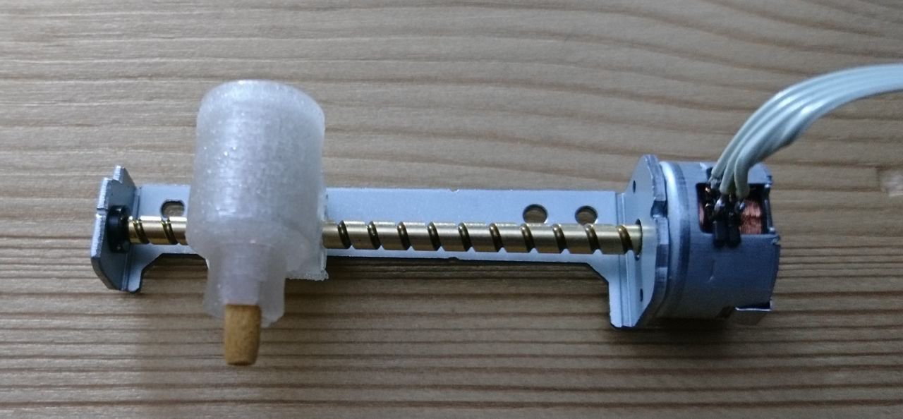
Oh yeah, the whole y-axis thing: I was intrigued by all those projects that used DVD drives to do CNC stuff, but all the wasted real estate by using the whole drive assembly as is was putting me off. So I studied how to replicate the DVD sled assembly, which meant buying sintered bronze bearings and integrating them into 3d-prints. In the end I had a very compact y-carriage whereas I would have had to support a humongous DVD-drive on top of that roll of masking tape.
The z-axis was originally just a printed tube in which a marker pen of a specific make could slide up and down without too much friction or wobble. But the PLA I used for the part soon contracted or some such and the pen was stuck. So I went to the effort of building a z-axis using two 3mm rods and bronze bearings being inspired by the axidraw plotter.
Doing so greatly increased the precision and enabled the machine to plot almost microscopically small letters (2mm height) using a very sharp pencil in the tool holder.
On the x-axis I am using a NEMA-17 stepper directly connected to the spool holder. As the 200 steps are nowhere close to the required angular resolution i simply went for the maximum amount microstepping (16x) and that worked out to be just about enough to not show visible artifacting.
I initially used the machine connected to a laptop running inkscape with the Hershey-Text plugin for the creation of the "artwork" and bCNC for turning it into gcode and for sending the gcode to GRBL. This proved to be impractical for the long run, because I tended to forget how to operate all the different bits and pieces that made up the working system. It also forced my to make notes at the place where I needed to have a label and then walk through the house to the computer and design the label and plot it out and then I had to walk back with the sticky label in my hand to apply it.
So I needed a self contained solution. I first found a bit of code that generated SVG from a string of text that I then could turn into gcode by another utitlity and then I used a self written gcode sender (IIRC). This worked with a laptop, but on the types of SOCs that I had lying around (RPis and Odroids of the first generations) this was way too resource intensive because hersheytextjs used nodejs, which took way too long to start up on those anemic machines.
So a bit later I found hf2gcode, which could directly produce gcode from a string of text. I also settled on an Odroid-C1 as I had some of those kicking around in a drawer together with matching 3.2inch LCD screens, so I only needed a keyboard and I was set. I chose a 2.4GHz wireless keyboard as I didn't want to deal with the headache of getting bluetooth running on the Odroid.
I also wanted battery power for my machine, so I used 3 18650 cells in series with a 3s protection...
Read more »


Hello! This is an amazing project and I have been trying to make one myself! However I am having trouble with the servo with the Z axis. I can control X and Y no problem through UGS but I cannot manage to make the servo move. It is a known working servo and it is not plugged into the Z axis next to the others, it is connected to GND and 5V on the opposite side of the CNC shield (just below the power plug). It is also connected to Z+. I had to modify the cpu_map file for Arduino Nano by changing the pins number to make the X and Y work so I was thinking maybe I need to do something similar to get the Z axis working? Any help would be super appreciated!!