The display in the 8060 is driven by a Sharp SM4a "4-bit microcomputer" which can do up to 68 segments with a 1/2 duty 1/2 bias drive. I didn't have a clear picture in my mind of the waveform that drives the display segments so I poked around a bit with my scope.
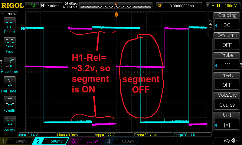
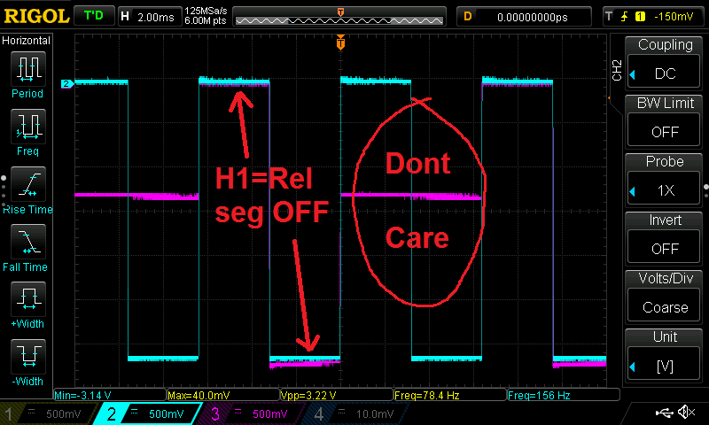
The drive signal is 0 to about -3.2v overall. The segment waveform is a ~156hz square wave, and the H1/H2 are stepped and out of phase with each other. When H1 or H2 and the segment waveform have a 3.2v difference (this will be for half of the H1/H2 cycle), that segment is ON. The other half of the cycle has a difference of 1.3/1.8v and the segment is OFF. The average voltage for the cycle is zero - otherwise the LCD would be damaged.
Here's a shot showing the drive signal for turning on the Rel segement, which is connected to the H1 common (notice that there is a delta of 3.2v - so it's ON - for 1/2 of the cycle):

Here's the signal when the segment is off (notice that no segments have a 3.2 volt delta):

 ogdento
Discussions
Become a Hackaday.io Member
Create an account to leave a comment. Already have an account? Log In.