Yann Guidon / YGDES
-
The flipping point
12/21/2016 at 01:20 • 0 commentsSo far I have received two kinds of flip-dot panels.
- A "PCB" type, where the coil is printed on the board. Very neat...
- A "wound" type, where the coil is made of enameled copper wound around the magnetic rod. Classic.
These two have different working points, as measured with a lab power supply:
- The PCB type starts to flip the dot when about 8V are applied to the coil. Add 0.7V (the unavoidable diode drop) and the LUMINATOR panel needs at leat 9V to operate. The nominal operating voltage is around 12V (compatible with my #YGREC16 - YG's 16bits Relay Electric Computer) but what's surprising is the operating current : the dot flips even down to maybe 20mA (the lab PSU goes in current-limit mode). I expected more... I suspect the PSU's output capacitors to store enough charge to create a current spike, so I'll have to test different configurations. Flipping power: less than 1/4W.
- The wound type (made in Germany) has a coil resistance of about 16.6 Ohms. The flipping current is around 130mA/2V, which means 3V or 3.3V with the diode. Flipping power: around 1/2W.
I'm amazed by the power efficiency of the LUMINATOR array. The printed coil is also more predictible and less subject to corrosion. OTOH the german displays are notably oxydized and several dots are damaged. I expected only one line (out of 19) to be unusable but mishandling might have occured and I can't get the 17 lines I wanted (16 data lines + parity, to spy on the memory).
Conclusion : if I give up on the extra parity line, the LUMINATOR is the best choice for my relay computer project. Thank you @Shaos for your precious help :-)
Now I have to examine the pulse characteristics...
-
Just Blow
12/20/2016 at 21:51 • 0 commentsI received a couple of different boards from Germany and wanted to test them, without and driver. I'm tired and lazy so I just blew over it :-D
-
Andere Anzeigen
12/09/2016 at 23:46 • 2 commentsGood news, european fellows : the magic of eBay has struck again :-D Look at these beauties:
- http://www.ebay.com/itm/122219644660
- http://www.ebay.com/itm/122219639759
- http://www.ebay.com/itm/Nr-3-ALPHANUMERIK-Display-Modul-Anzeige-GORBA-flipdot-Mercedes-Omnibus-O-405-/162276918727
- http://www.ebay.com/itm/schmal-ALPHANUMERIK-Display-Modul-Anzeige-GORBA-flipdot-Mercedes-Omnibus-O-405-/162276919895
Like the previously seen LUMINATOR arrays, they are 28 dots wide, but 19 dots high instead of 16. That's why I took the display with the three broken dots : it's cheaper and I don't need the bottom 2 rows. That's 17 lines and I can still show the parity bits :-)
OK I also ordered the pristine one. But the seller still has other modules for sale at the time of writing (the 2 last links). Watch the seller http://www.ebay.com/usr/motozentrum in case more became available...
![]()
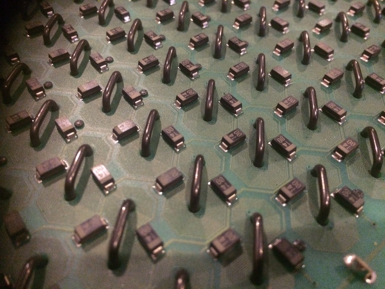
The shots of the back show the pairs of steering diodes and the matrix is very simple so I expect no surprise. I can un-socket the IC and do my things...
Unlike the LUMNATOR the PCB doesn't implement the magnetic coil, so I'm curious.
Ô the things I could do with them... ;-)
-
Actual boards
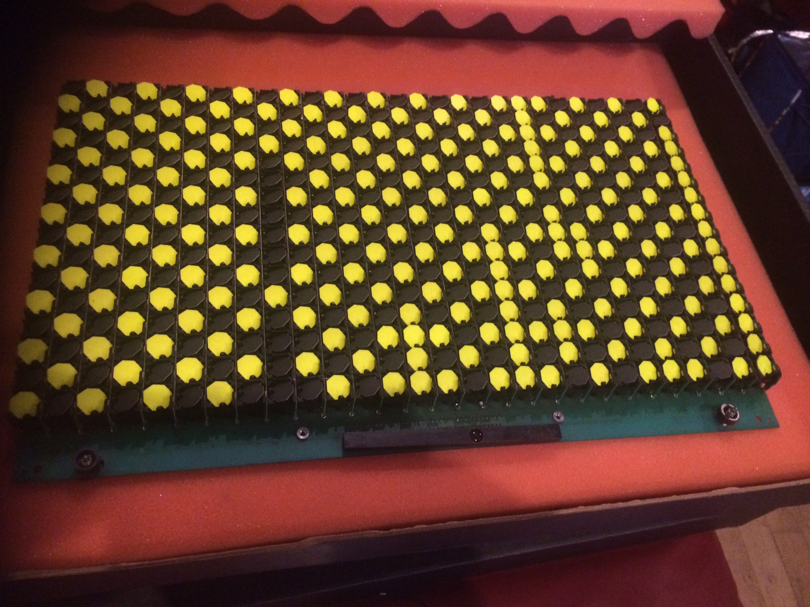
11/30/2016 at 06:51 • 8 commentsI've got actual boards today:
![]()
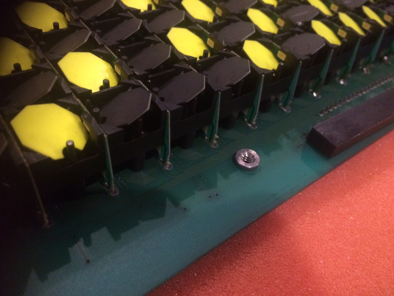
Close look from the front:
![]()
And the back:
![]()
-
Some progress
11/30/2016 at 03:27 • 0 comments@Shaos got boards !
He also shared some informations he dug, such as https://github.com/hshutan/45x7-flipdot-controller: we learn more details about flip voltage (10-15V) so it's right in my range of +/-12V (though there is one more diode drop, which could be reduced with a Schottky).
I'm also curious about the following remark : ".... there is little risk of a flip dot being energized for more than a few hundred microseconds"
I don't know the cycle time of my machine but I was anxious that the pulse would be too short. I thought a dot would need a pulse that would last something like 100ms but Harrison implies that it's in fact shorter. Given that the RES15 relays have a propagation/latency of around 3.5ms, it's actually a good margin yet not excessively long... We'll see !
Maybe it's a coincidence but hackaday.com has just published a story about modern flip dots screens, the expensive kind...
http://hackaday.com/2016/11/29/flip-dot-displays-appear-with-modernized-drivers/Oh and have a look at the gorgeous dots at https://github.com/hshutan/45x7-flipdot-controller
-
Wild guesses
11/27/2016 at 01:23 • 7 commentsI don't know when I'll receive my modules but I have found an online source of some Luminator Max 3000 arrays. 16 lines, 28 rows, this is perfect for my system. But how do we drive them ?
I've found a youtube video that seems to be a very similar model.
The implication is clear : it's a "typical" array, almost.
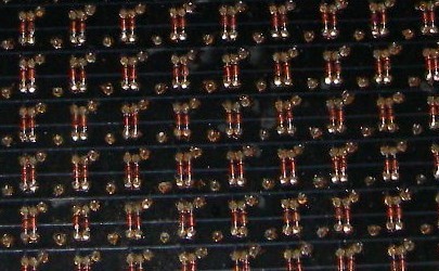
But there is a bit more than that, when looking closer.
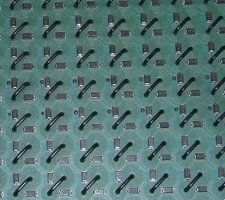
![]()
We can see on the backside that there are 2 diodes per dot. So it's not a typical array like with LEDs. The solenoids must be driven in one direction or another, which is not the case with a classic diode array.
I have found an interesting description there http://electronics.stackexchange.com/questions/243030/how-to-drive-315-coills-in-flip-disc-display/243054 but I have independently come up with a little different approach that is suited to relay technology.
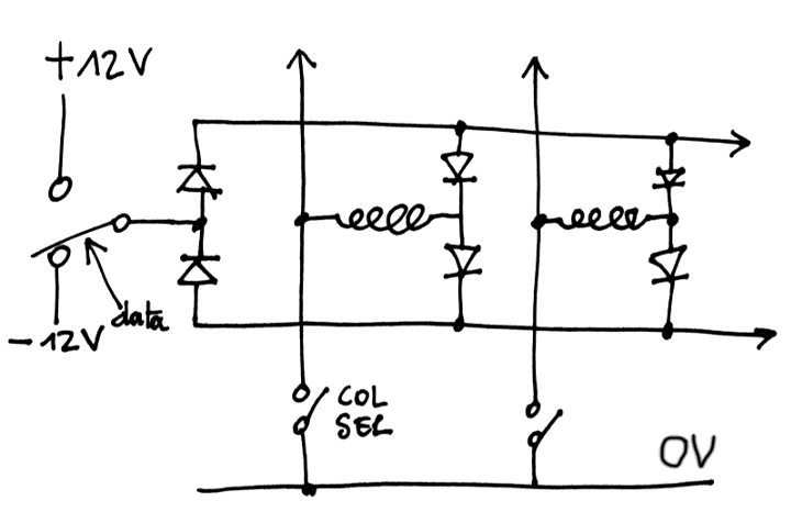
![]()
The +/-12V symmetric supply is already used for the DRAM bus of the #AMBAP: A Modest Bitslice Architecture Proposal but there is a difference : the column select switches to 0V, not -12V (which is required by the electrolytic polarized capacitors). The data driving circuit is shared with the data bus, but a separate column selector must be wired. A couple of diodes must also be added for each data line.
For semiconductor technology, it's quite simple as well : a high-side PNP or P-FET and a low-side NPN or N-FET will be enough, no need of a diode.
Of course, it must be tested.
PS: the diodes are not strictly required, if you drive one end with a high-side to +Vcc and the low-side to -Vcc. However the above circuit diagram requires the diodes because I get the data directly from the write bus of AMBAP. It already drives the data line at these levels to recharge the DRAM's capacitors. Without the diodes, the current wouldn't be correctly steered...
Dot flippers
or "flip dotters" if you want. Let's just talk about flip-dot/flip-disc displays and projects using them :-)