I've been working slowly on the firmware side, although free time is becoming a rare commodity on my side.
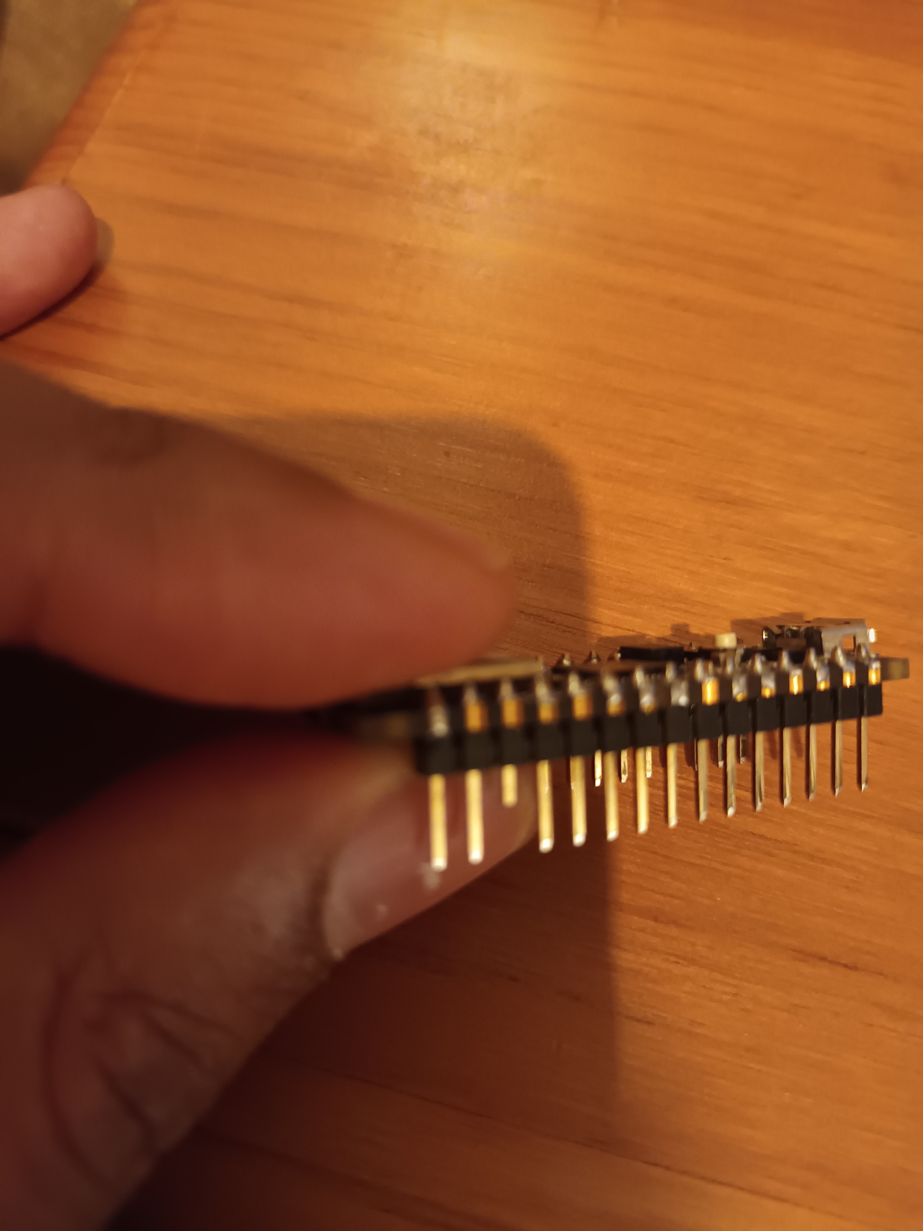
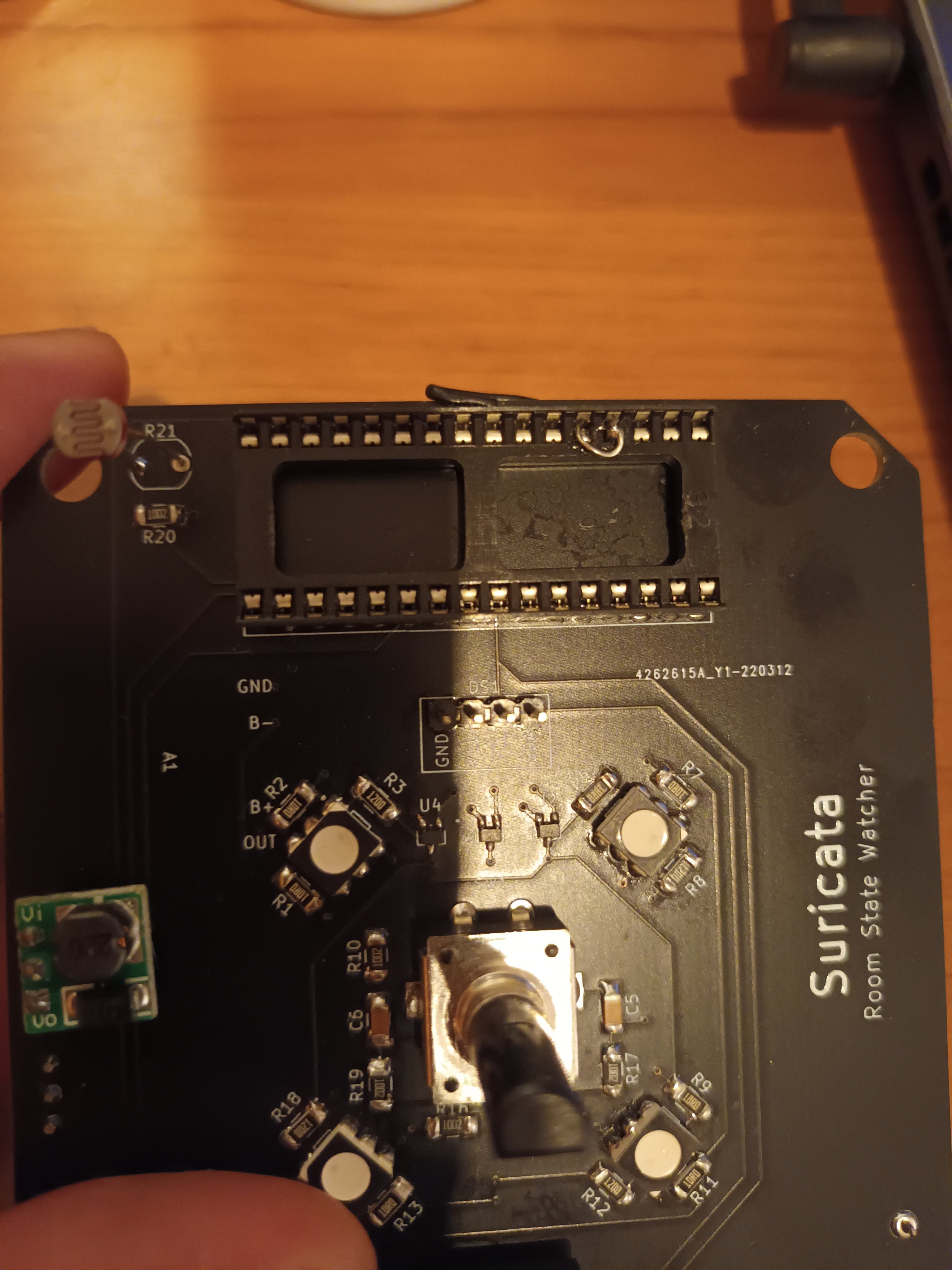
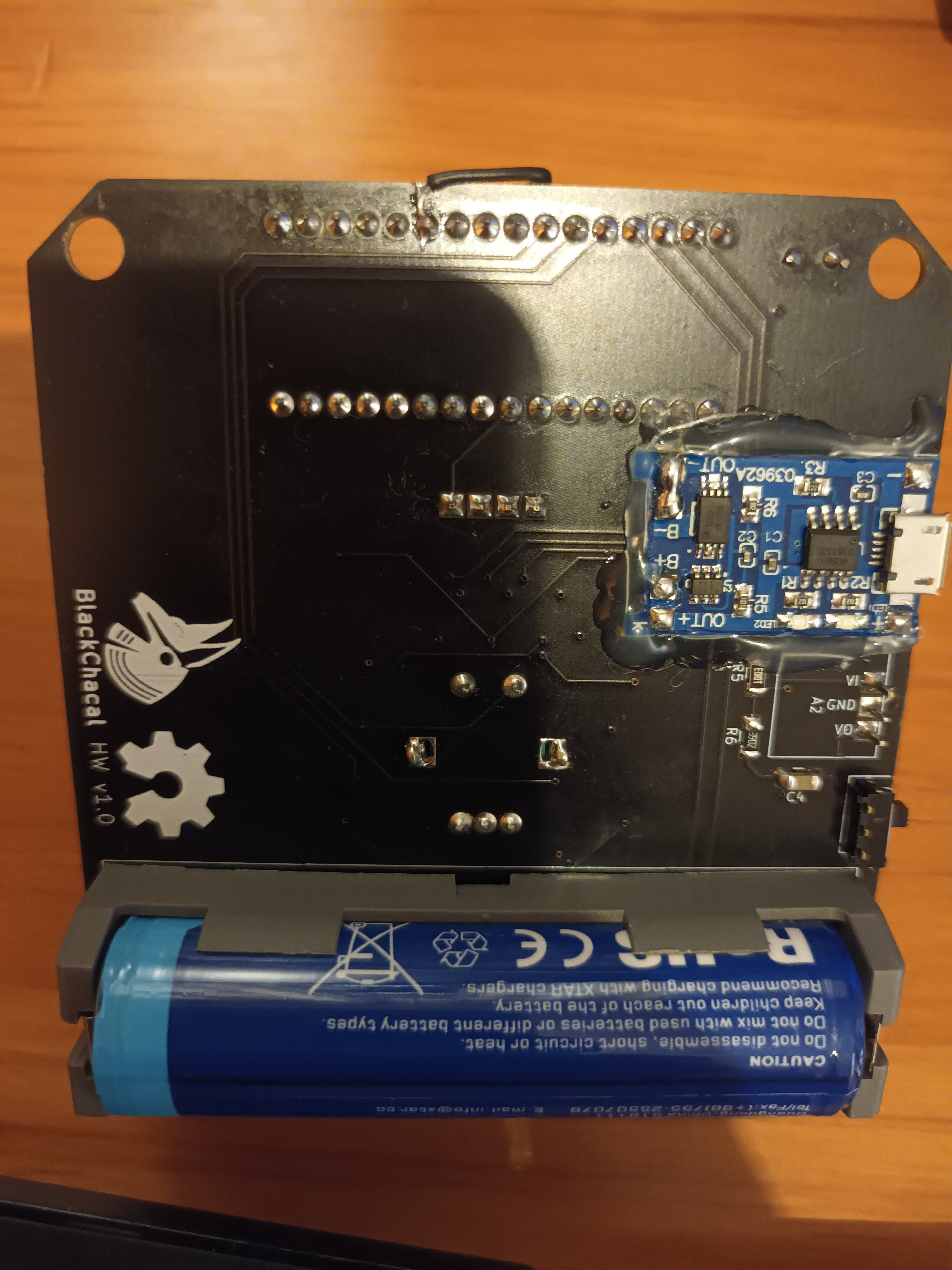
While starting the firmware development I noticed a few more schematic and PCB mistakes. One of them was major. During schematic I misplaced one position in a few Arduino socket pins. I ended up connecting the GND plane to the Reset pin instead of the GND pin. This left the Arduino on reset. I had to cut the Arduino reset header pin to prevent it to touch the socket. I also had to shunt two socket pins, and break the buzzer lane and connect it to the right pin with a wire to the PCB bottom.


The other mistake was again a footprint inversion. I ended up flipping the buzzer polarity. It does not seem to work at the moment, probably it is broken. Have to do a little more debug on that. Definitely, there must be a PCB version 1.1.
Besides this, everything else so far seems to be working fine. I only haven't tested the screen and rotary encoder.
At the moment, I've already done the LDR, LED, MIC and DHT20 drivers. I can read their values and print on the serial console. The LEDs can also turn on/off, blink at chosen frequencies and fade in/out. For the LDR and MIC I tried to calculate the LUX and sound intensity in absolute dB, but the values are not correct. For the LUX I tried a quick calibration using a mobile phone lux meter app, but I need more points to find the right calibration curve. For the sound intensity I used the mic datasheet data and a few equations for the conversion but something is off. I will fix it later.
Right now, Suricata is ALIVE!!!
 Ricardo Tonet
Discussions
Become a Hackaday.io Member
Create an account to leave a comment. Already have an account? Log In.