 Steve Smith
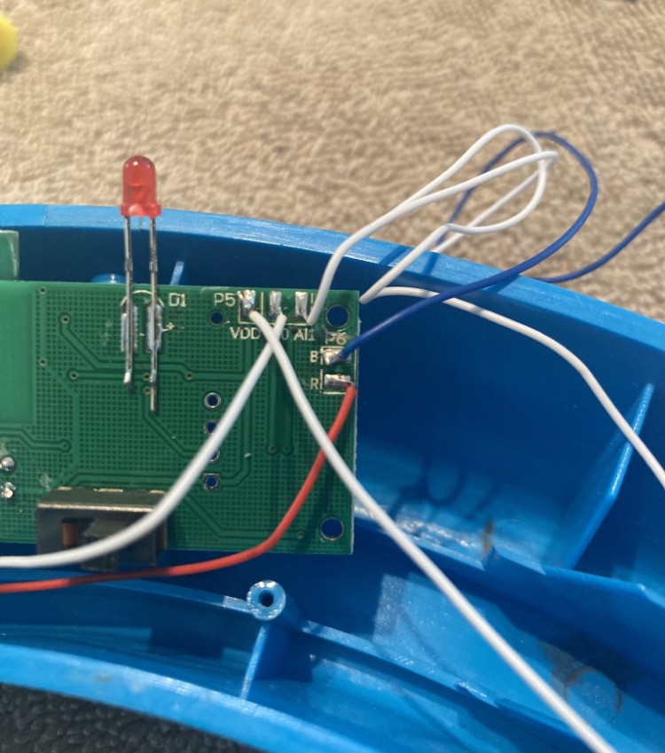
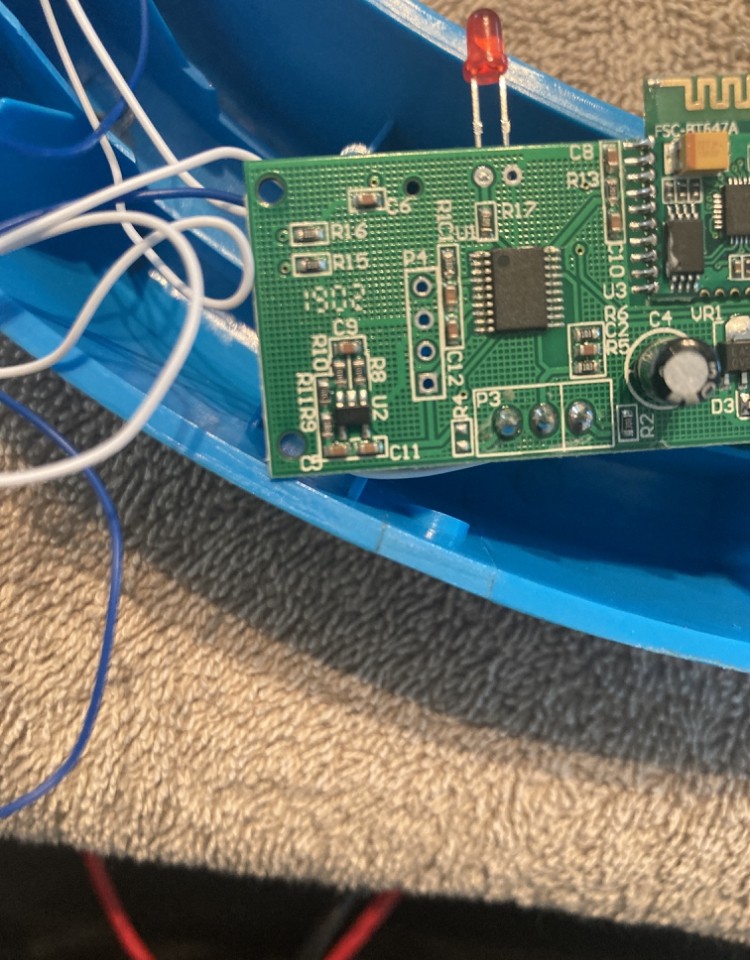
I started off this project by trying to understand how the existing scale platform was electronically connected. So I just started drawing a sketch based on iphone pictures that I took of the PCB and load cell wiring. It was an UGLY view into basically a 3 way Strain gauge wired as a WheatStone bridge of sorts. The big ah-ha moment was that there were few 3 strain gauge load cell wiring diagrams on the internet......but after deciphering their PCB, I noticed that they filled in the fourth strain gauge with just passive resistors that were trimmed to equal the series resistance of the other 3 strain gauges. So I had a VERY UGLY but preliminary sketch and that was a good start!

Discussions
Become a Hackaday.io Member
Create an account to leave a comment. Already have an account? Log In.