 Dimitar
So... why going through the trouble of making a BMS. Simple, because I could not find one that would fit the flat batteries and also I needed to add one anyway for electronic CV project.
The BMS is based on AP9101C. There are a lot of examples circuits, it is being out for nearly 4 years and you can by it almost everywhere. The last one is very important nowadays. The MOSFETs I chose were DMN601DWK again cheap and easy to find. The schematic is the exact same one that you can find in the datasheet, but still you can find mine here.
There is one very important gacha! You should be very careful which modification you get. Take a close look at "Voltage and Delay Combination" table. Most charger go up to 4.28 V voltage and nearly 1A of current. So if you get something like AP9101cxxx-COTRG1 you will be out of luck. The overvoltage protection will kick in and your battery would not charge. Also when you connect the BMS to the battery for the very first time, you will get 0V. It does not matter if you have fully charged battery. You will need to connect a charger to release the AP9101C from "storage" mode.
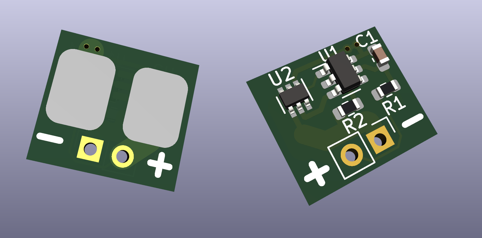
A few word on the design:
- Make it small
- Mark the pads well
- Add 2.54 header pads for the output.
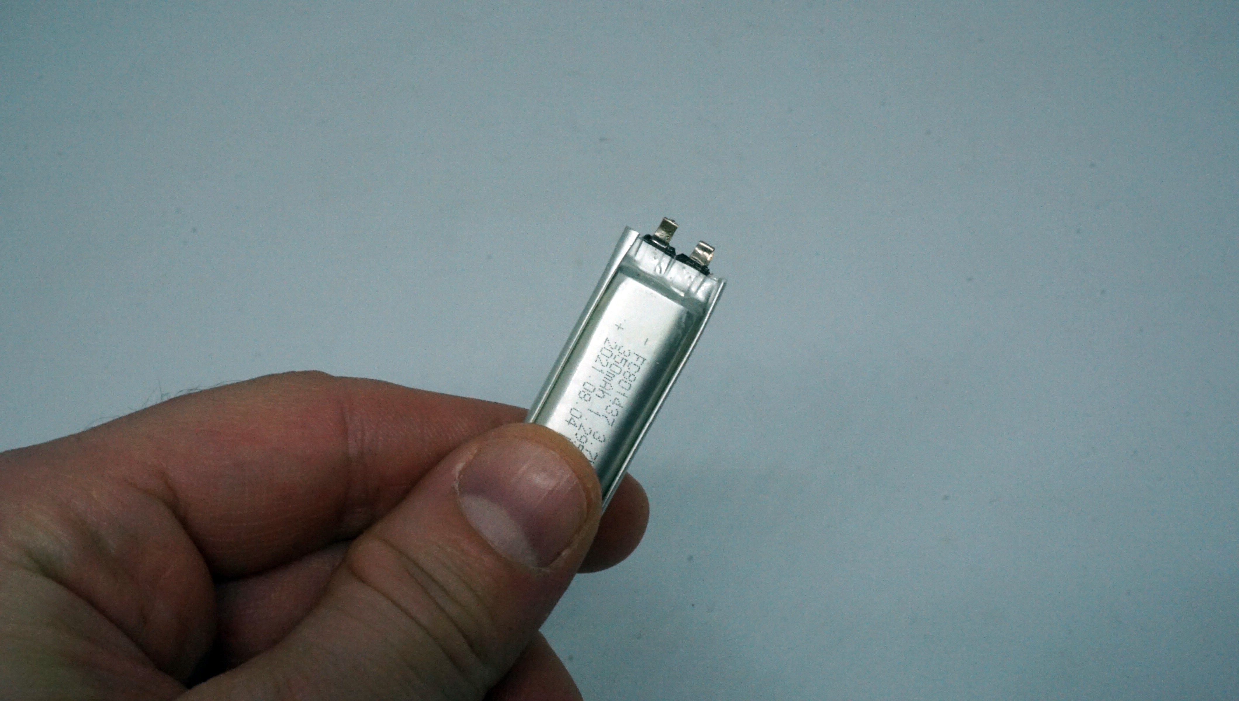
- Make the pads for the battery as big as possible, because the batteries' terminals very
If there is a significant demand I would make them available on tindie. So leave a comment if you want to get one.
Cheers,
Mitko
Discussions
Become a Hackaday.io Member
Create an account to leave a comment. Already have an account? Log In.