Close
0%
0%

Weaver Modular Component System

A collection of reusable modules that implement various electronic circuit functions

Similar projects worth following
112 views
0 followers
Electronic waste is a serious problem as devices are typically obsoleted in a few years. The assemblies combine many small components, made from a wide variety of materials, and thus are not well suited for recycling. To avoid creating electronic waste, reuse makes more sense, when many components have a useful life of 50 years or more.

The maker world has created many electronic modules, but interfaces are inconsistent, mounting is often not considered, and many simple components don’t seem to be well supported as modules. Interconnect systems are often not suitable for application to production devices. A more consistent and robust approach is required for the adoption of modular electronics to become widespread.

This project will define a comprehensive system of modules that will assemble without solder, and can be disassembled easily for reuse.

The first couple of board batches have been primarily human-machine interface (HMI) and interconnect components.

The HMI component collection so far includes:

  - 5mm LED

  - 5mm bicolour LED

  - button

  - LED/button

  - pot

  - multi-position switch (4 positions)

  - toggle switch

  - rotary encoder

All of these components can be panel mounted. The boards convert the pin connections into a Grove/4 pin JST PH or 2 pin JST PH connector. In some cases resistance is added eg for LEDs. The boards are extremely simple, and the layout time was minimal. The boards are small, so the cost is low when buying in volume.  

The composite HMI is wired with PH and Grove cables, which can optionally be consolidated into byte-wide breakouts. Then a 10-wire JST PH connector is used to carry signals back to the MCU. 

M3 or #4-40 standoffs and screws are used for mounting. I chose #4-40 over M3 because we have a local supplier that stocks these and they are cheap. 

While this concept may use more parts, it all comes apart and there is very little waste. The only part that cannot be easily reused on this first demo HMI is the acrylic panel.

There are a lot of other kinds of components that should integrate using the same methods of mounting and interconnect. Displays, keypads, communications interfaces, motors, storage, and so on. 

All of types of modules are available in some form, and when components already exists that fit the design pattern, then these will be specified rather than creating new modules. In some cases I will be creating carrier boards that provide the desired interconnect, mounting, and other features, so that the components are easily integrated.

Also there are a variety of simple boards required in support of interconnect. 

  • Interconnect Boards

    Tom Dowad06/10/2022 at 16:54 0 comments

    A variety of simple boards are required in support of cabling. These typically convert between the three connector sizes, convert into 0.1" spaced connectors, extend cables, bus cables, and so on. 

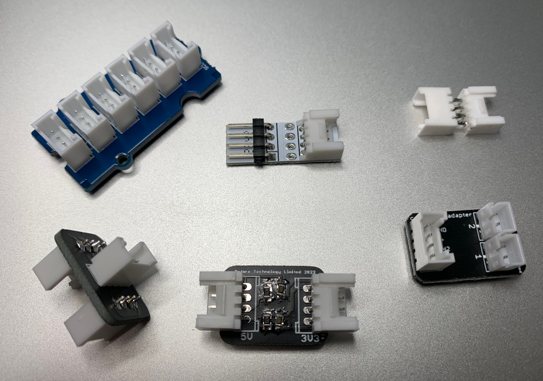
    Firstly, there are two boards the were already available. The Grove bussed connector board from Seeed (useful primarily for I2C expansion) and the M5 Stack Grove-to-0.1" board. The M5 Stack boards can be purchased from Digikey and are inexpensive. Its a clever design where the 0.1" side can snap off and you then have 4 holes which you can use as you see fit. I took advantage of this feature and stacked two of them, making a tap for connecting my logic analyser. One nice thing about building circuits with modules is that its easy to tap into cables for monitoring signals, kind of like test points being built-in.

    The other boards I've made could be partially summarized as convertors between the cable formats. That is, 10-to-2, 10-to-4, and 4-to-2. 

    I made a 4-pin merger. For any peripheral device that uses only one signal line and a 4-pin connector (eg a pot), then it might be useful to merge two of these onto one 4-pin cable. That one signal will always be on the first signal pin, and so the merger takes two of these in, and puts one signal onto signal 1 and the other onto signal 2. 

    A similar pass-thru board with just two connectors  ought to be created as a cable extender. I've made cable extenders by taking two 4-pin connectors and soldering their pins together, though this is not going to be robust so a board is better. 

    I made a board with two 4-pin connectors and resistive dividers to reduce signal voltage, typically to 2/3rds for converting 5V to 3.3V. Its a cheap way to do it, but I think I will make one using proper level shifters. 

    Something missing from this collection is a convertor from 4-pin to various 0.1" pitch pinouts. There are many modules available, for sensors, actuators, and so on, that use 0.1" pitch headers, and the pinouts vary. I believe there are 12 permutations of 4 pins to 4 pins. I tried making one with solder jumpers in a matrix, so that any in/out combination was possible. But it was too big. I want the adapter to disappear into the part. 

    One approach would be to replace the header pins with a JST XH connector, with 0.1" pitch, then make a special cable with XH on one end and Grove or PH on the other. But that seems painful. I think having a set of very small boards that cover all the useful permutations would be better. Then all of these devices can be converted to be system-compatible. 

  • Cabling & Connectors

    Tom Dowad06/10/2022 at 16:47 0 comments

    So far the cabling system consists of 2, 4, and 10 wire cables. I have considered  adding a 6-wire cable for SPI, but the 10-wire will suffice for that. I'm trying to avoid creating a need to stock more different parts, and the 10-wire connectors are small enough (and wires don't need to be stuffed if not needed). The connectors can all be JST PH, with a 2mm pitch. 

    However, the 4-pin cable I prefer is Grove ie Seeed Studio's standard cable, which also has a 2mm pitch. These can be purchased from Digikey so are easy to come by. They are good for I2C, serial, LED strips, quadrature encoders...anything requiring two wires...and also GPIOs, analog, and so on.

    The 2-pin cable is a JST PH. I am using these for contact closure, LED outputs, speakers, etc.  Some PH cables can be purchased on Aliexpress, but as I wanted a variety of lengths, I found a supplier using Alibaba and ordered several hundred direct from the factory. 

    The 10-pin is a JST PH. Its 8 signal lines, power, and ground. A board is available to convert this to a 0.1" pitch Dupont style connector. The 10-pin Dupont cables were purchased from Aliexpress. I'm finding the 10-pin to be useful for consolidating several of the smaller connectors into a byte.

    All three styles of connector shell have a plastic tab holding each wire, and its easy to temporarily bend up the tab, release the wire, then put it back in different position or different connector shell. I find this very useful. I've not had good luck with connectors that have a metal retaining tab. 

    If you use PH through out, then it is easy to move the wires around between different width connector shells.  One might just as well buy the crimped wires without the shells, and put them in the shells as needed. The PH has a slightly lower profile then the Grove, which helps as space in an enclosure is often a problem.

    But the colour coding of Grove is helpful, the cables are easy to come by, and there are a variety of companies offering products using Grove. For instance, Sparkfun's I2C system, QWIIC, has a Grove adapter cable, so bridging into that system is easy. Moving wires on a Grove connector is easier than on a PH.

    I think generally the boards are best to have unstuffed (ie not pre-assembled). Yes that breaks the solderless concept. In practice I'm finding 1. the boards are so simple they solder together in minutes and 2. there are a variety of ways to put together a board eg using right angle vs straight connectors, male vs female, putting connectors on the other side of the board etc. Since the Grove and the PH have the same footprint, the user can make that choice when assembling. Then for instance one could bridge into STEMMA or DFRobot Gravity,  which use the JST PH as well. 

    A note regarding the connector orientation on the boards: the polarization slots should point inward, to allow for right angle or straight connectors to be used. Right angles always have the slot on the top. 

View all 2 project logs

Enjoy this project?

Share

Discussions

Similar Projects

Does this project spark your interest?

Become a member to follow this project and never miss any updates