Close
0%
0%

LCD Solar Creatures

Solar-powered creatures that react to energy with animations on a 7-segment LCD. And they blink at night!

Similar projects worth following
The Solar Creatures are based on a simple 7-segment LCD display and an ATTiny85 microcontroller. They store their energy in a pair of 1.5F supercapacitors that can power them through the night.

When the sun shines, the display plays lively animations: a tiny version of Conway's Game of Life, or randomized rhythmic patterns. As the light fades, the animations slow down, and at night the creatures use their high-power red LED instead to beam out a rhythm. The Creatures draw 11.4μA, 7.3μA and 6.2μA in these modes, respectively.

The Solar Creatures are infused with patterns through and through. The animations and the flashes are all randomly parameterized Euclidean rhythms. You will rarely see the same show twice!

They recognize the periodic peaks and lows of energy, and they keep track of their own age in days. They faithfully report this to you in between two animations, and they also tell you how long they were awake in the last few days.

Schematics, design files and source code are available in the project's Github repository.

Meet Window Squatter and Desktop Crawler

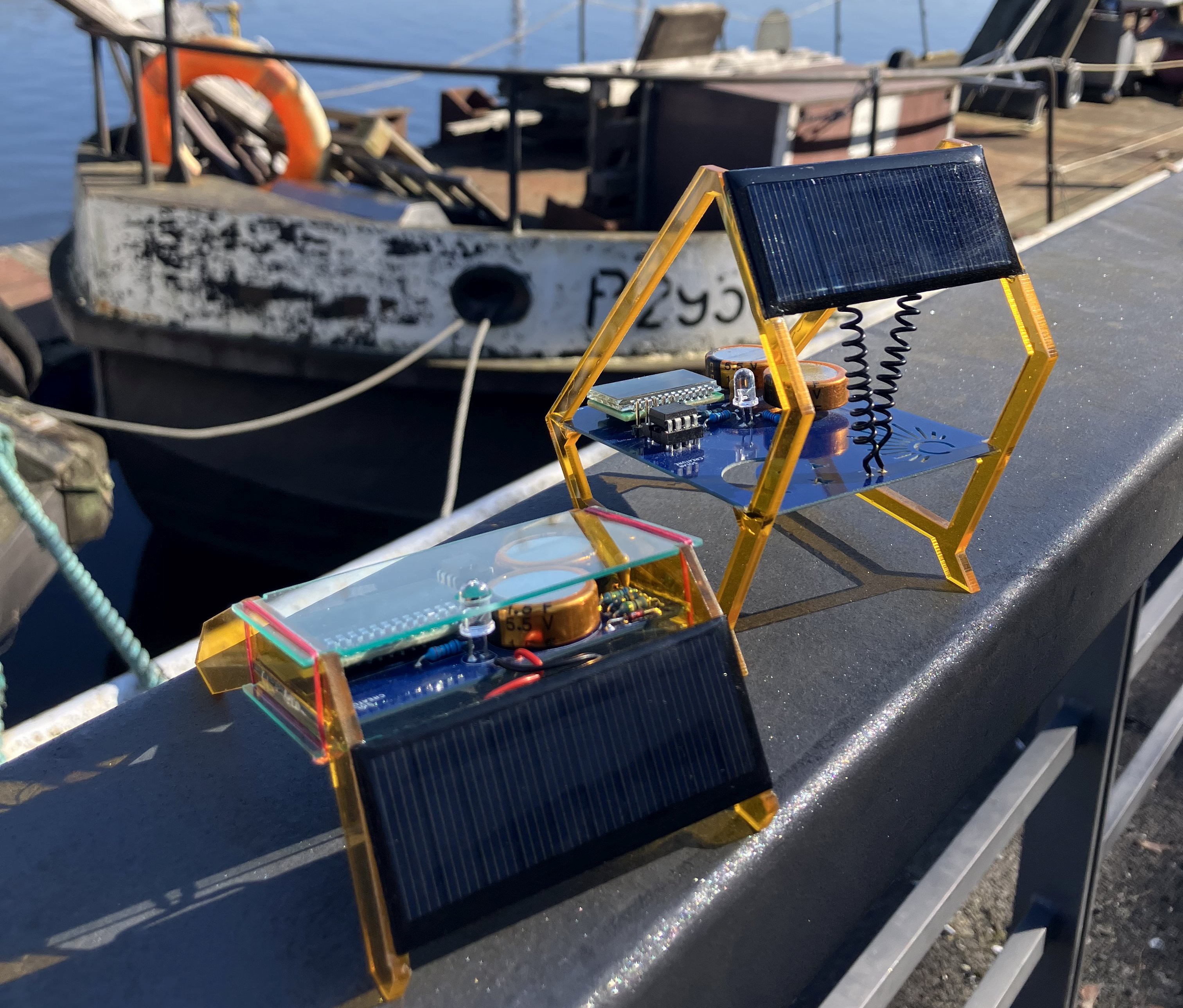
The creatures come in two shapes, but their circuitry and programming is identical. The window squatter (which less generous souls have also called the beach chair) reaches up to catch the sunlight if your window has a thicker frame. The desktop crawler's natural habitat is a desk or shelf that gets a lot of direct sunlight. Here you can see them side-by-side at the pier on a recent sunny day.
Built of circuit boards and acrylic

  • The blue circuit board is the centerpiece of both creatures, because, hey, technology is beautiful! The PCB is particularly pronounced in the window squatter, where it goes wild with a sun & moon cutout.
  • The frame is laser-cut from 3mm orange acrylic. The desktop crawler adds a top+bottom cover cut from 1mm blue-ish transparent acrylic.
  • Both creatures are accessible for hacking and repair! The squatter exposes pins to measure voltage or reset the ATtiny. The chip itself can be removed from a socket so new firmware can be flashed onto it. The desktop crawler's covers are not glued in place but tied together with a fine fishing line. At one point the capacitors will die, but this way it's possible to go in, unsolder them and put in a new pair.
  • The solar cell is a 30x70mm 5V or 6V piece.
  • The LCD... Oh, the LCD from AliExpress with the weird segment-to-memory mapping! Read the build log for the juicy details.

Conway's Game of Life on a 7-segment LCD

Here's the Desktop Crawler playing an adapted version of Conway's Game of Life. The neighborhood rules create an infinite playing field that wraps around at the edges. Perhaps because of this, the simulation often reaches cycles that can be anywhere from 2 to 10 steps long. Up to a length of 4 the Creature detects loops and invokes the Chaos Monkey to randomly flip two positions. Usually this nudges the simulation towards a different stable state.

Euclidean rhythms

Here's a Creature playing a Euclidean rhytm for four voices. The rhythm's parameters are randomized every time a new animation starts.

Status report

In between animations, the Creatures give a quick update about themselves. How many days have they been alive? What's the current voltage of the supercaps? How long have they been awake today? How long they were awake yesterday, and the day before, and the one before that?

A beacon at night

Come night, the capacitors slowly drain. When the voltage drops below 3.3V, the LCD switches off and the Creature goes into ultra-low-power mode. Only the strong red LED blinks out a rhythm a few times a minute. The rhythm changes from night to night.

A tribute to classic solar circuits
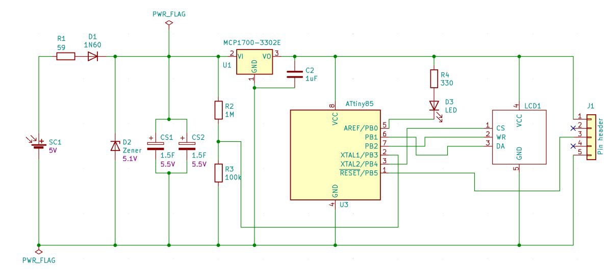
  • The 1N60 Germanium diode, the 5V Zener and the small resistor are standard fare for solar projects with a supercap. The 1N60 has a low forward voltage and it makes sure the solar cell doesn't discharge the capacitor when it's dark. The Zener protects the capacitor from overvoltage.
  • The rest of the circuit is behind an MCP1700-3302E LDO voltage regulator, so it never runs at more than 3.3V. That is part of how the creature saves power: the ATtiny's current draw is much less at lower voltages.
  • R2+R1 divides the capacitor's voltage down so the ATtiny can measure it against its internal 1.1V reference voltage.

A program that spends (almost) all its life asleep

  • The creatures spend most of their life sleeping. They have a faithful watchdog timer to wake them up regularly, so they can update the ongoing animation.
  • There are different programs active depending on the voltage level. Above 4.1V it's all lively animations with Euclidean rhythms or an adaptation of Conway's Game of Life. Between 3.3V and 4.1 it's just a smiley face, and a quick status report about days alive, voltage level, hours awake, and hours awake in the past three days.
  • Under 3.3V, till shutdown, it's a flashing light. Yes, the flashes are also guided by...
Read more »

  • 1 × ATTiny85 microcontroller
  • 1 × 4-digit, 7-segment LCD display with HT1621 controller
  • 1 × Solar cell 5V 70x30mm
  • 1 × Zener diode
  • 1 × Supercapacitor

View all 12 components

  • Reverse engineering my new LCD

    Gabor06/25/2022 at 14:51 2 comments

    OK, “reverse engineering” is a bit of an exaggeration here, but that was essentially the vibe when I first hooked up my mystery LCD component to an Arduino Nano.

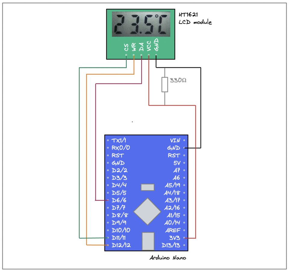
    I’m not big on either Fritzing or Eagle, so I made a sketch of the wiring for you in Excalidraw :) The only thing that might need some explanation here is the 330Ω resistor between GND and the Nano board’s 3.3V output. I’m powering the board over USB, which is 5V. The 3.3V output comes from the on-board voltage regulator, but with no load I’m getting a higher voltage. The LCD component doesn’t like that: the off segments are turning black at a normal viewing angle. So I just did the easiest hack I could think of and added the resistor to create some load on the 3.3V VCC pin. This helps just enough, so I’m leaving it at this.

    A bit of googling lead me to Valerio Nappi’s ht1621-7-seg library, so I went and wrote up a sketch that counted rapidly from 0 to 9999, took a deep breath, and uploaded it to the Nano. Here’s what happened:

    That is actually... splendid news! The board can clearly talk to the LCD component, information is getting transmitted, and the display’s segments get turned on and off in response.

    All that’s left is to figure out which bit in the library’s buffer corresponds to which segment on my display, because apparently this component is wired very differently from what Valerio was working with.

    The magic in the library essentially boils down to this code snippet:

    void HT1621::wrData(uint8_t data, uint8_t cnt)
    {
     uint8_t i;
     for (i = 0; i < cnt; i++)
     {
       digitalWrite(PIN_WR, LOW);
       delayMicroseconds(4);
       digitalWrite(PIN_DATA, (data & 0x80) ? HIGH : LOW);
       digitalWrite(PIN_WR, HIGH);
       delayMicroseconds(4);
       data <<= 1;
     }
    }
    

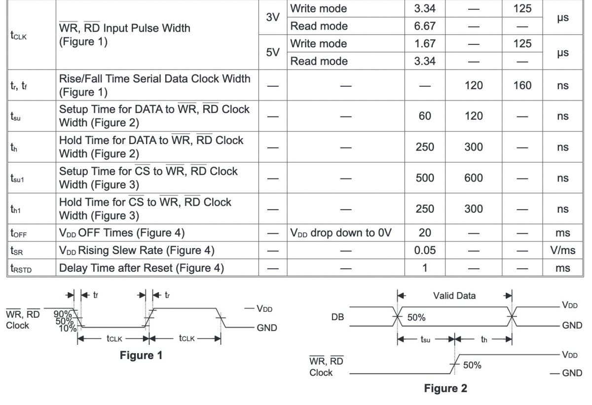
    The loop transfers cnt number of bits from data, starting with the highest-order bit and moving right. This technique of controlling the levels on the communication pins straight from code is called bit-banging, and it’s a straightforward implementation of the wire protocol described in the HT1621 datasheet:


    The 4 μs delay on the clock signal is at the lower end of what HT1621 accepts for writing, but hey, who wants to waste time saying nothing?

    As I was experimenting I altered and reduced Valerio’s code in various ways:

    • The original library has a 6-byte buffer, and always transmits all of it when updating the display. For some related display drivers that can control more segments this makes sense. But with my 32-segment LCD, only 4 bytes are ever used, so I reduced the buffer and don’t transmit the always-zero 16 bits during updates.
    • The original class stores the index of the 3 pins it uses in memory, which makes sense in a general-purpose library. I switched to defines for this, eliminating another 3 bytes from my program’s memory footprint. This matters in the ATTiny85, where I only have 128 bytes! I’ll want to use them for cool animations and other funky behavior in the creature.
    • I removed all functionality related to encoding digits and characters and moved that to a separate class. I consider that a different, higher layer; my HT1621 class only deals with controlling the display’s segments based on the bit values in a 4-byte buffer.
    • I rewrote the command codes in binary notation, as that mirrors the specification in the datasheet more transparently than hex values. And I totally kept the Chinese comments, which must date back to anxzhu’s original library that Valerio forked :)
    #define BIAS    0b01010010 // 1/3 duty 4 commons
    #define SYSDIS  0b00000000 // 关振系统荡器和LCD偏压发生器 ~ disable sys oscillator and LCD bias
    #define SYSEN   0b00000010 // 打开系统振荡器 ~ enable system oscillator
    #define LCDOFF  0b00000100 // 关LCD偏压 ~ disable LCD bias generator
    #define LCDON   0b00000110 // 打开LCD偏压 ~ enable LCD bias generator
    #define XTAL    0b00101000 // 外部接时钟 ~...
    Read more »

  • Low-power LCD is... hard!

    Gabor06/12/2022 at 11:42 0 comments

    Simple, 7-segment monochrome LCDs have been on every cheap calculator and digital wrist watch for decades, so you'd think they are the easiest component to find for a low-power electronics project... But they are not! In reality, this has probably been the part of where I spent the most time looking for a solution.

    There is no shortage of easy-to-use display modules for microntrollers if you're looking for an OLED display or even a 7-segment LED display. These are fun, but they are definitely not low-power.

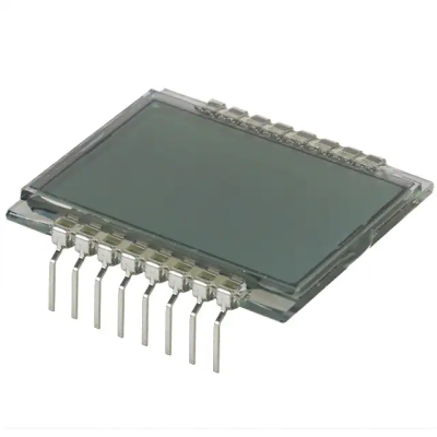
    Then there is an abundance of bare-bones LCD displays without a driver. These are parts with lots and lots of connectors, looking a little something like this:

    They are cheap, readily available - and a real pain to use. It's not just the sheer number of wires, though that's an issue as well. The problem with an LCD is that you cannot just send power to the right pins and hope for things to work out. You need to actively send alternatig signals to prevent irreversible chemical changes inside. People have done it before and written about it, and it makes for a really interesting read too: Driving an LCD display directly with ATtiny. But I'm not ready to bikeshed this from scratch.
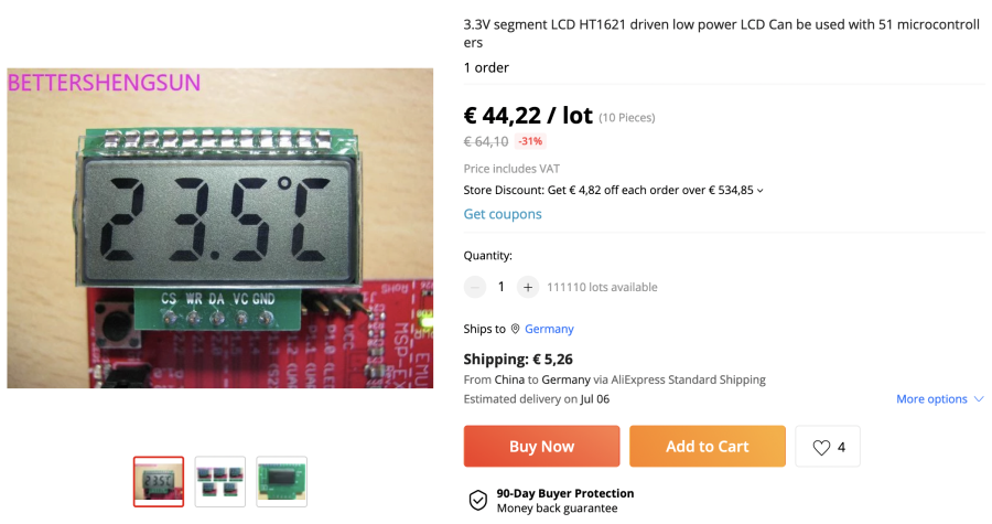
    And I don't need to, either: there are ready-made components to drive an LCD. After a great deal of searching I zoomed in on the HT1621, which seems to be the most widely used one for small displays with up to 32 segments. I could get one of these and hook it up with a bare-bones LCD display, except... The HT1621 has a lot of pins, and it comes in an extremely tiny form factor. Just to get started I would need to get a custom PCB manufactured, and I'm pretty convinced I wouldn't even be able to solder parts this small. I need a breakout board.

    Which is where things get really, really difficult. It's exactly these breakout boards that seem to barely exist. Mohit Bhoite has apparently found one for his latest satellite, but it's unclear where it comes from. Maybe it's this part from Hexpert systems? There's something inside me that rebels against spending 12 bucks on what's supposed to be a super simple mass-produced component. [UPDATE: Mohit just tweeted about this, and it's exactly as I thought: his satellite uses the part from Hexpert.]

    And so I turned to Aliexpress, where I eventually struck gold. The link will most likely be gone soon, so here's a screenshot of my bounty:

    44€ might sound like a lot, but it's for a bag of 10, and I think when I placed my order it was more like 30€. Anyway, these postings come and go all the time and the price of the exact same product varies a lot, so it's worth searching around!
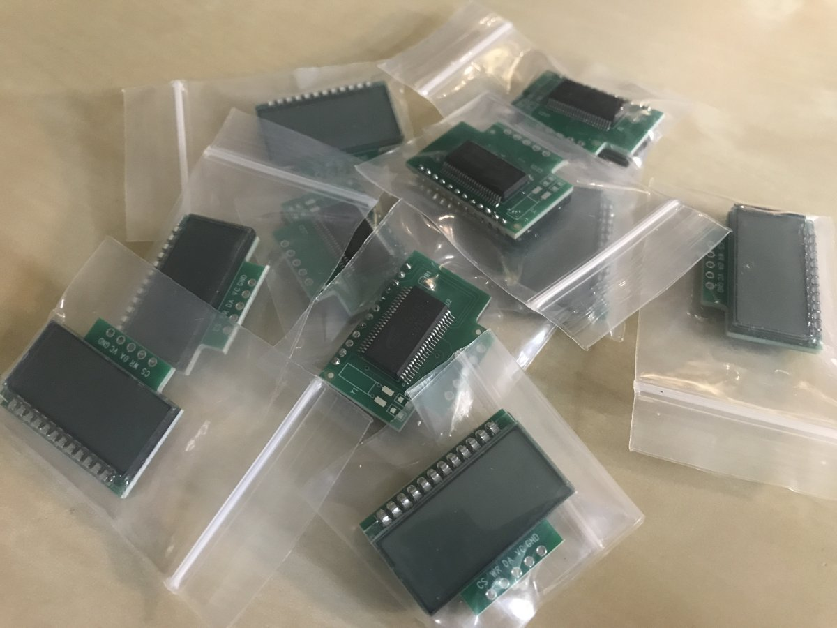
    I placed my order, crossed my fingers, and waited... And true enough, in about four weeks I had a padded envelope in my mailbox with a literal bag of 10 of these things.


    NOW the fun can start! But that will be a separate update.

    Useful links:

View all 2 project logs

Enjoy this project?

Share

Discussions

cp wrote 03/14/2023 at 23:15 point

Great project.  Would you consider sharing the source code?  I am particularly interested in the source for measuring the voltage.  Thanks!

  Are you sure? yes | no

Gabor wrote 03/14/2023 at 23:57 point

thanks! sure thing, check out the linked github repo, it's all there!

  Are you sure? yes | no

Similar Projects

Does this project spark your interest?

Become a member to follow this project and never miss any updates