 Neil Lambeth
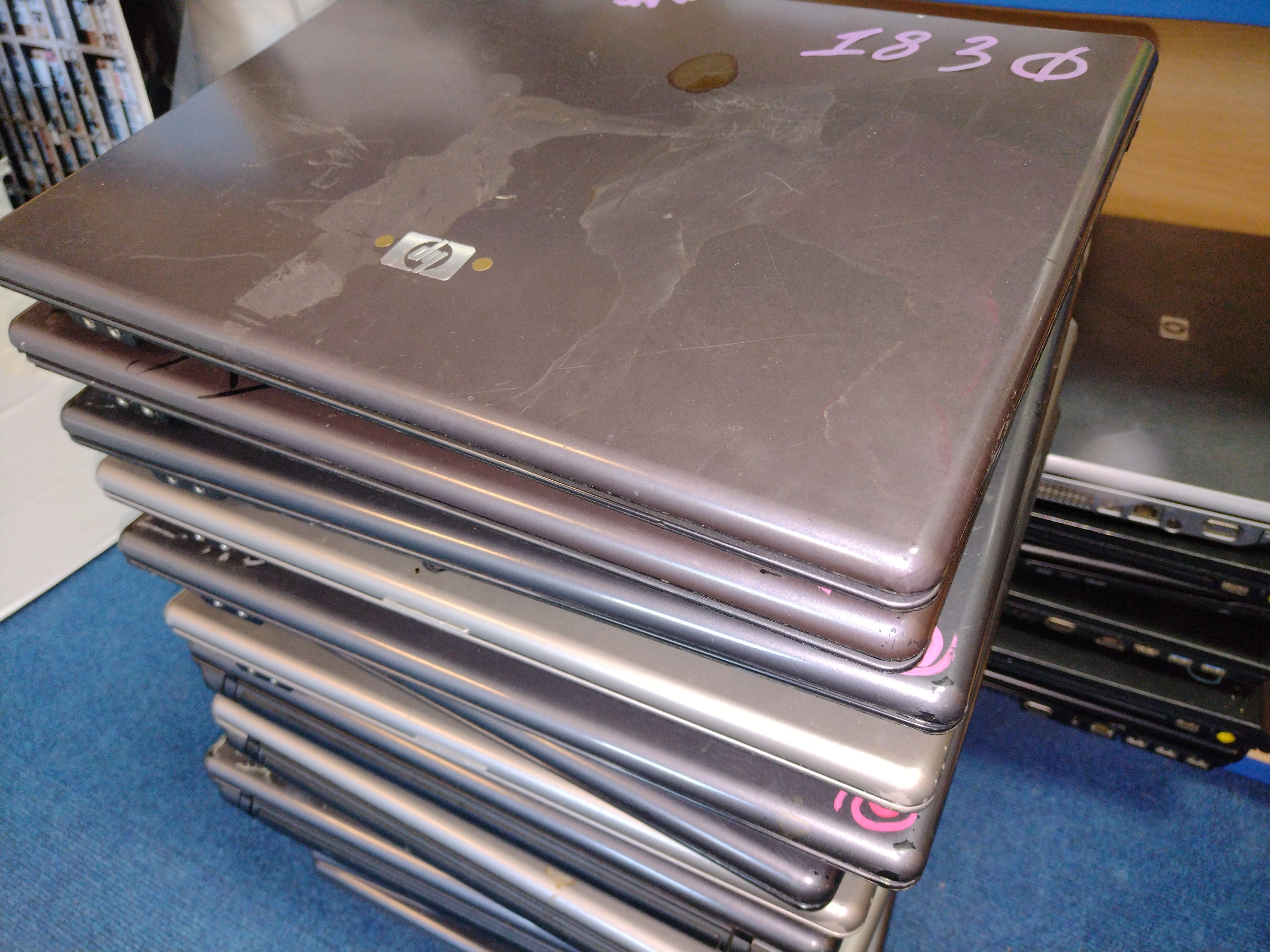
I've been given about 30 HP550 laptops. These are old and battered and perfect for turning into new X-PCs!
I also wanted to test my FreeCAD model with another laptop, to make sure everything works as it should.
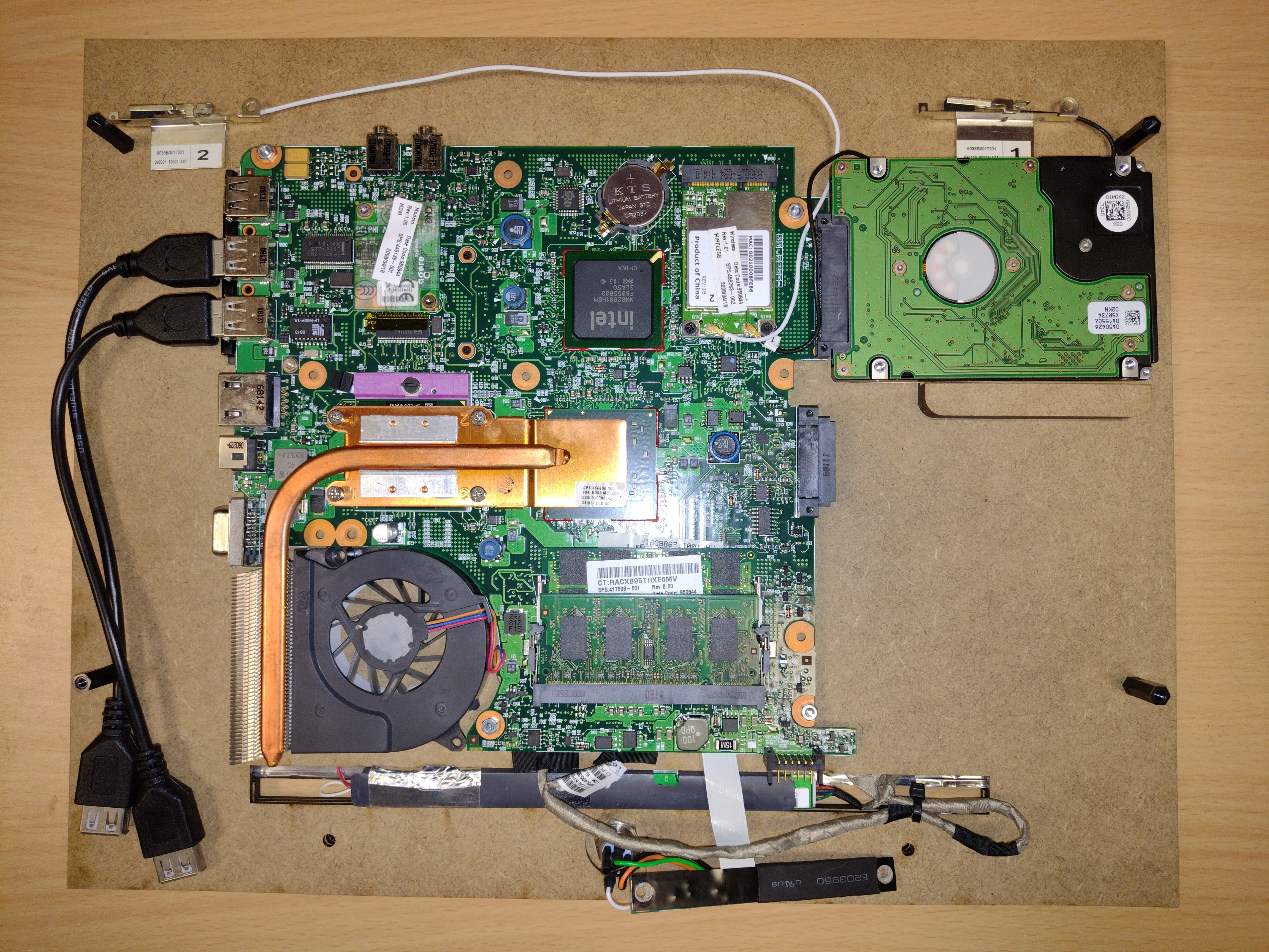
I stripped down one the laptops, removed all the parts, then checked that everything still worked.
I then measured the screen width and height, and the size of the PSU. I entered these parameters into the FreeCAD model and generated the 2D layout for the laser cuter.
Once I'd cut the parts out, I set about positioning and mounting the motherboard.
Each laptop is going to be different, for this one I had to make a little shelf for the hard drive to sit on to keep it supported.
I made this with some off-cuts of MDF.
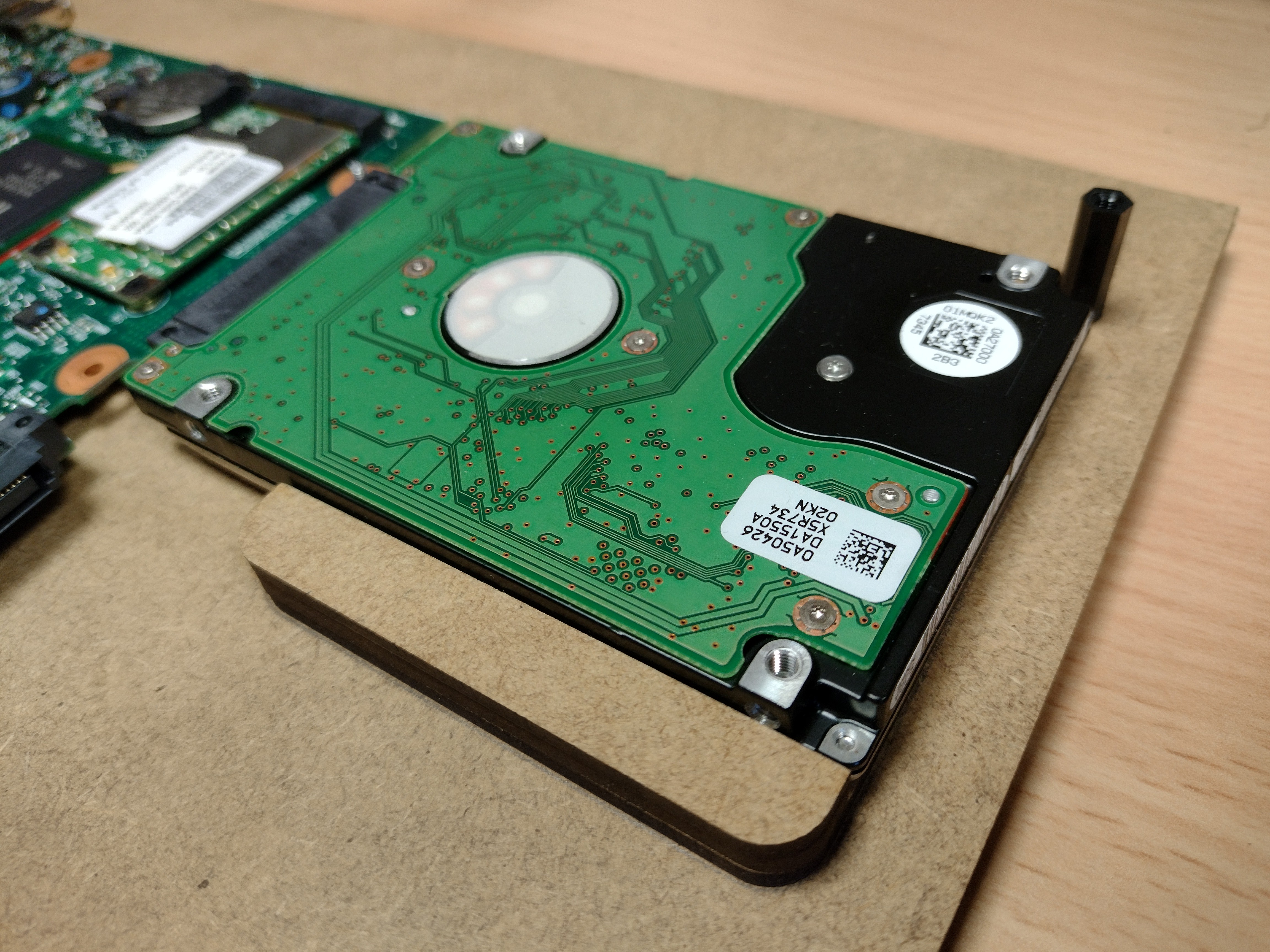
I then put a screw through the motherboard cover to attach a standoff - to stop the HDD sliding out.
The power PCB looks different but works in the same way. I removed the button and LED with a hot air gun.
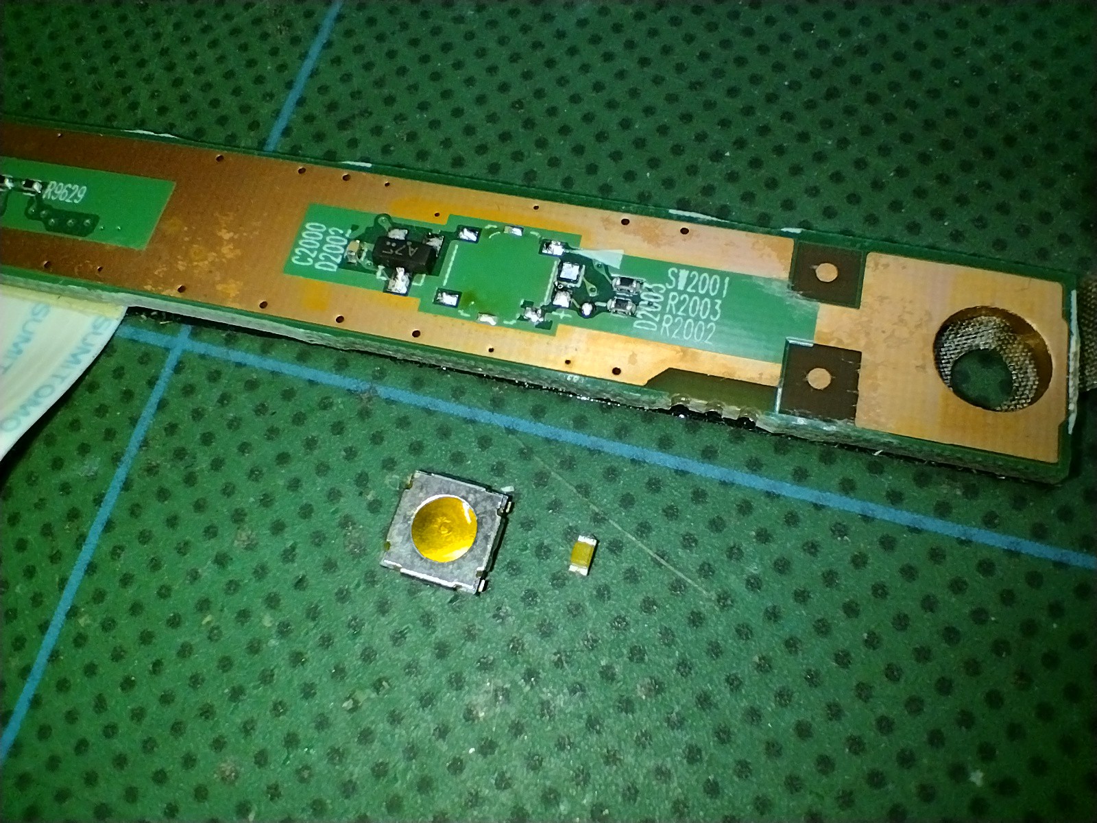
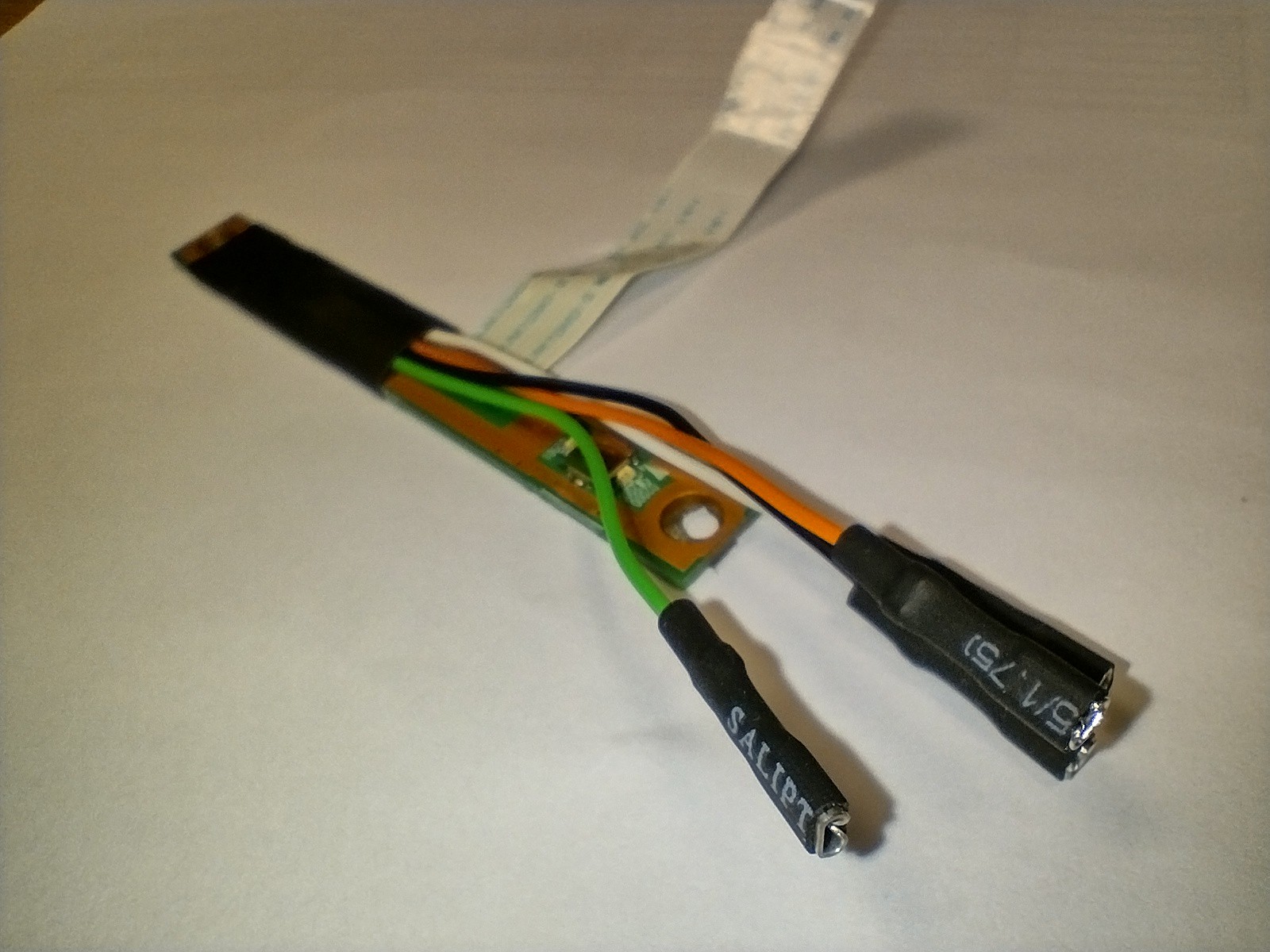
Then soldered on the wires.

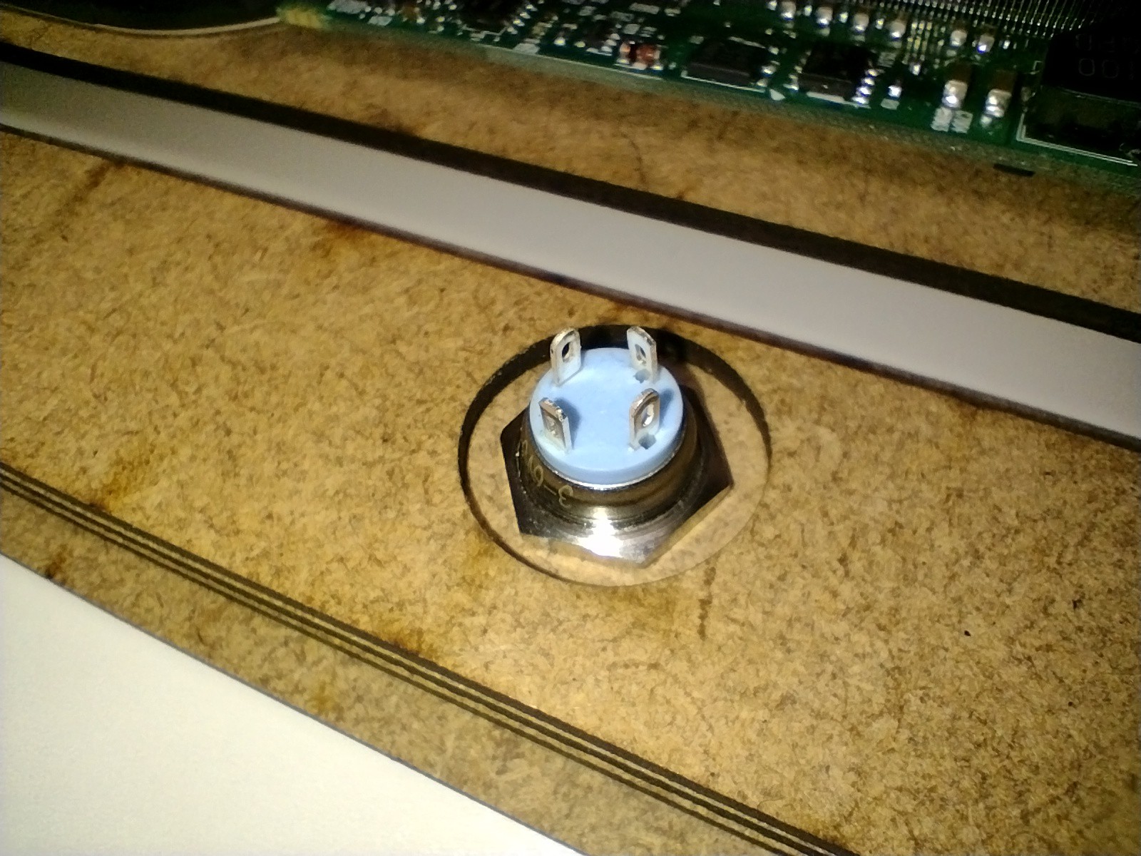
I then attached crimp terminals to the ends of the wires - this makes it mush easier to attach them to the switch terminals, and remove the switch if necessary.
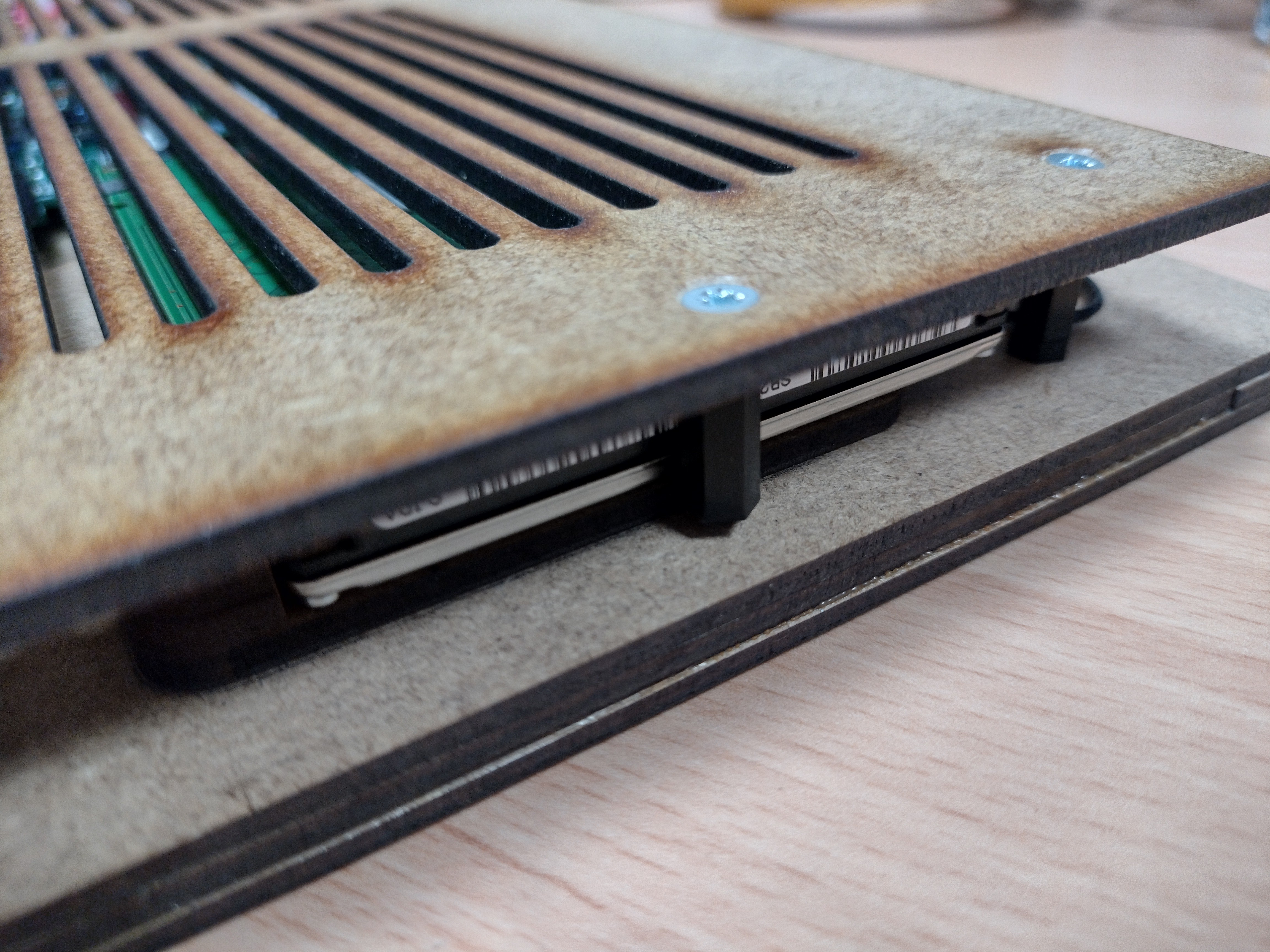
I then put the rest of the frame together, everything worked perfectly!
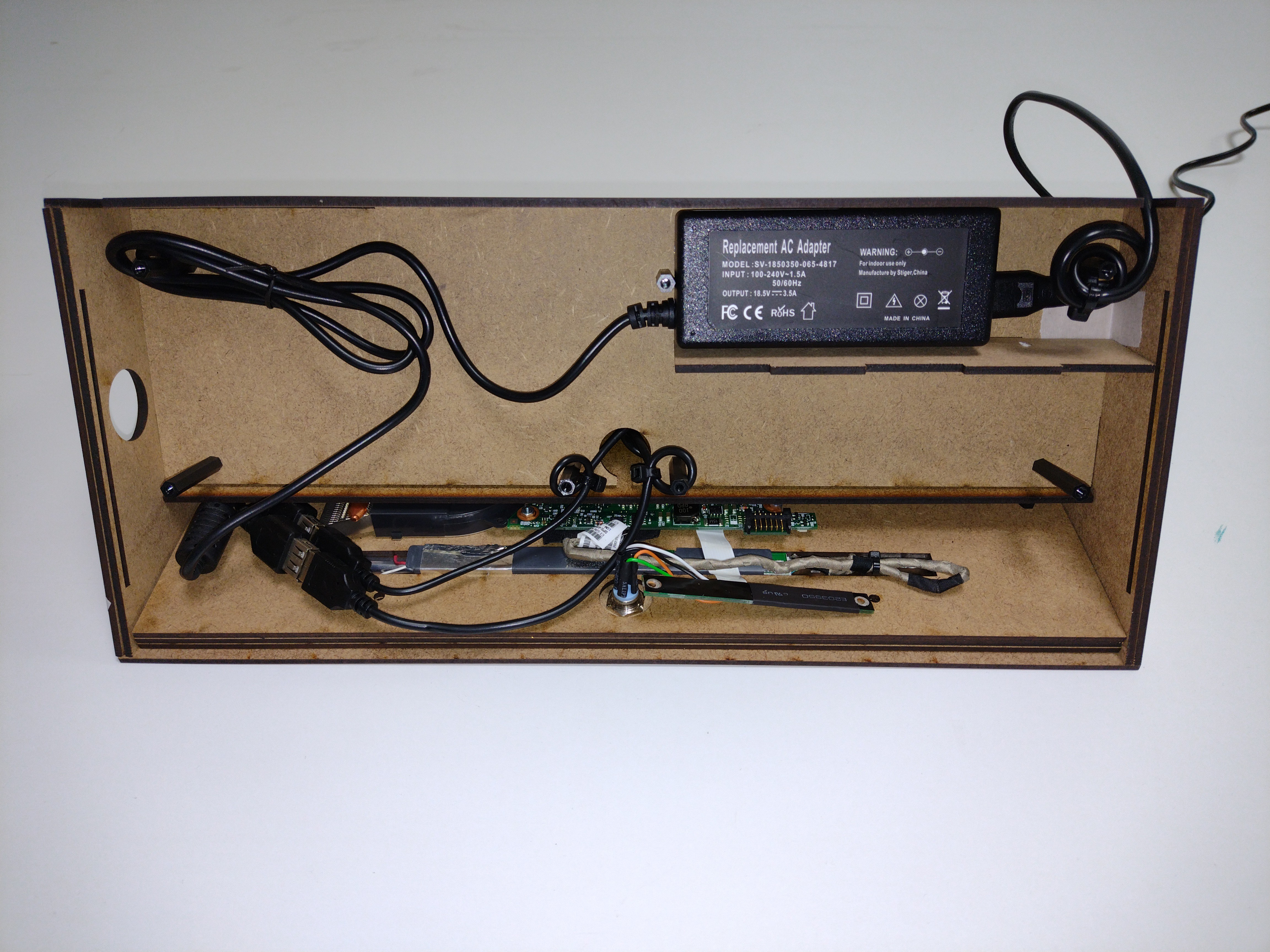
Here's the view from the underside showing all the parts in place. I ran out of the dash mount USB/headphone connector, but it's not needed for this test.
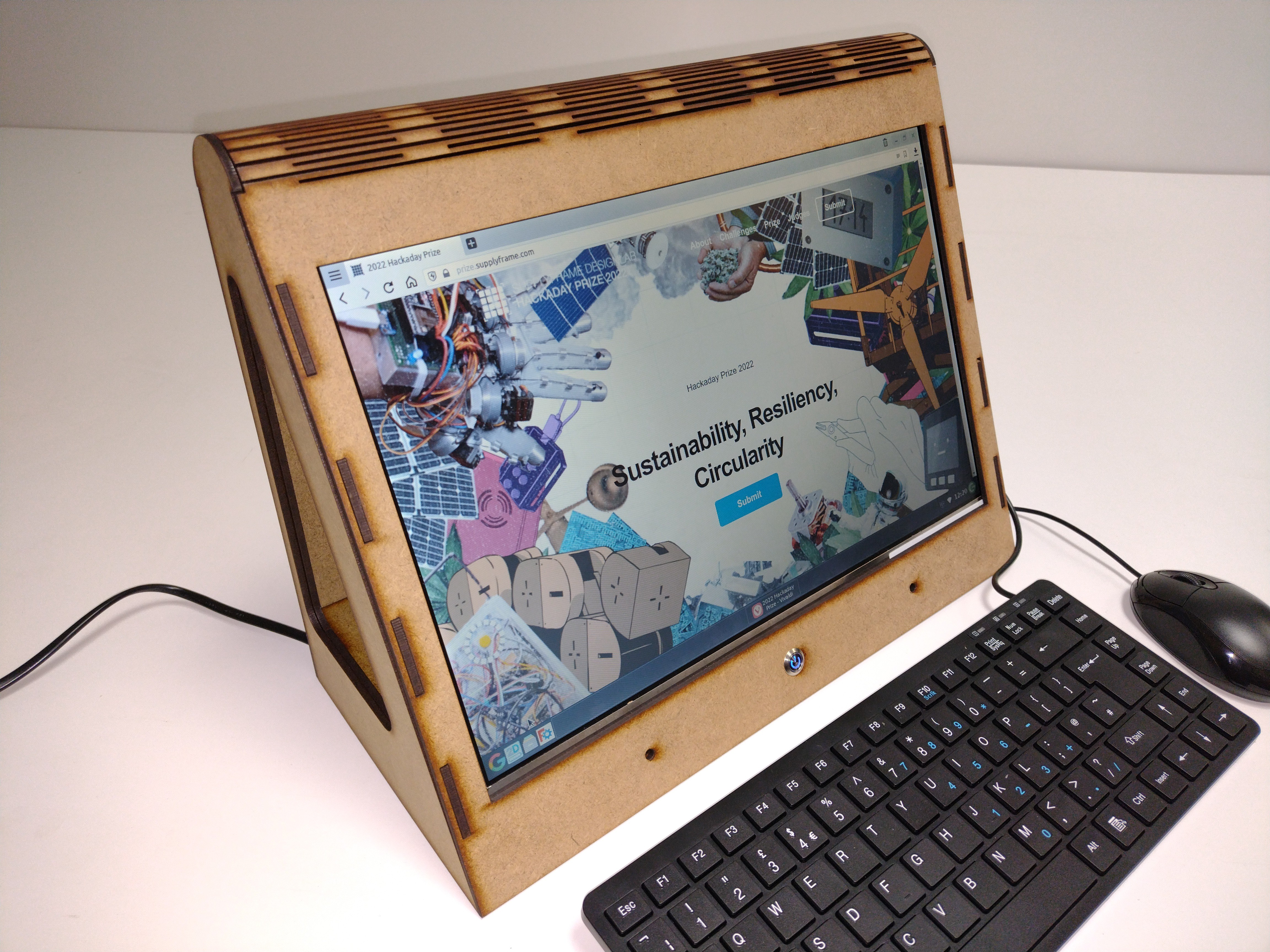
And here's the finished prototype. It worked first time!
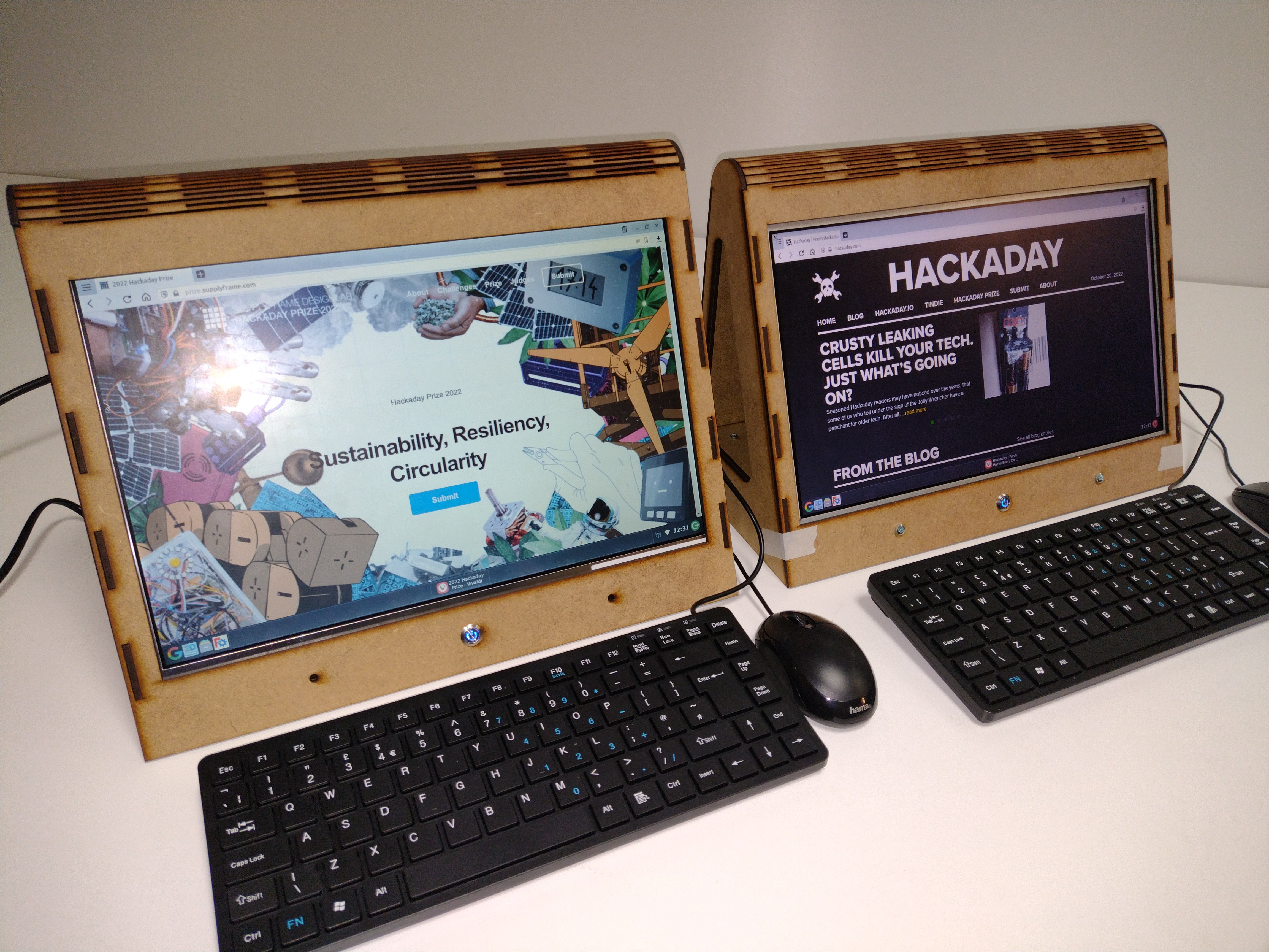
Here are my two X-PC 2 prototypes side by side for comparison. HP550 on the left, and Lenovo B590 on the right.
Discussions
Become a Hackaday.io Member
Create an account to leave a comment. Already have an account? Log In.