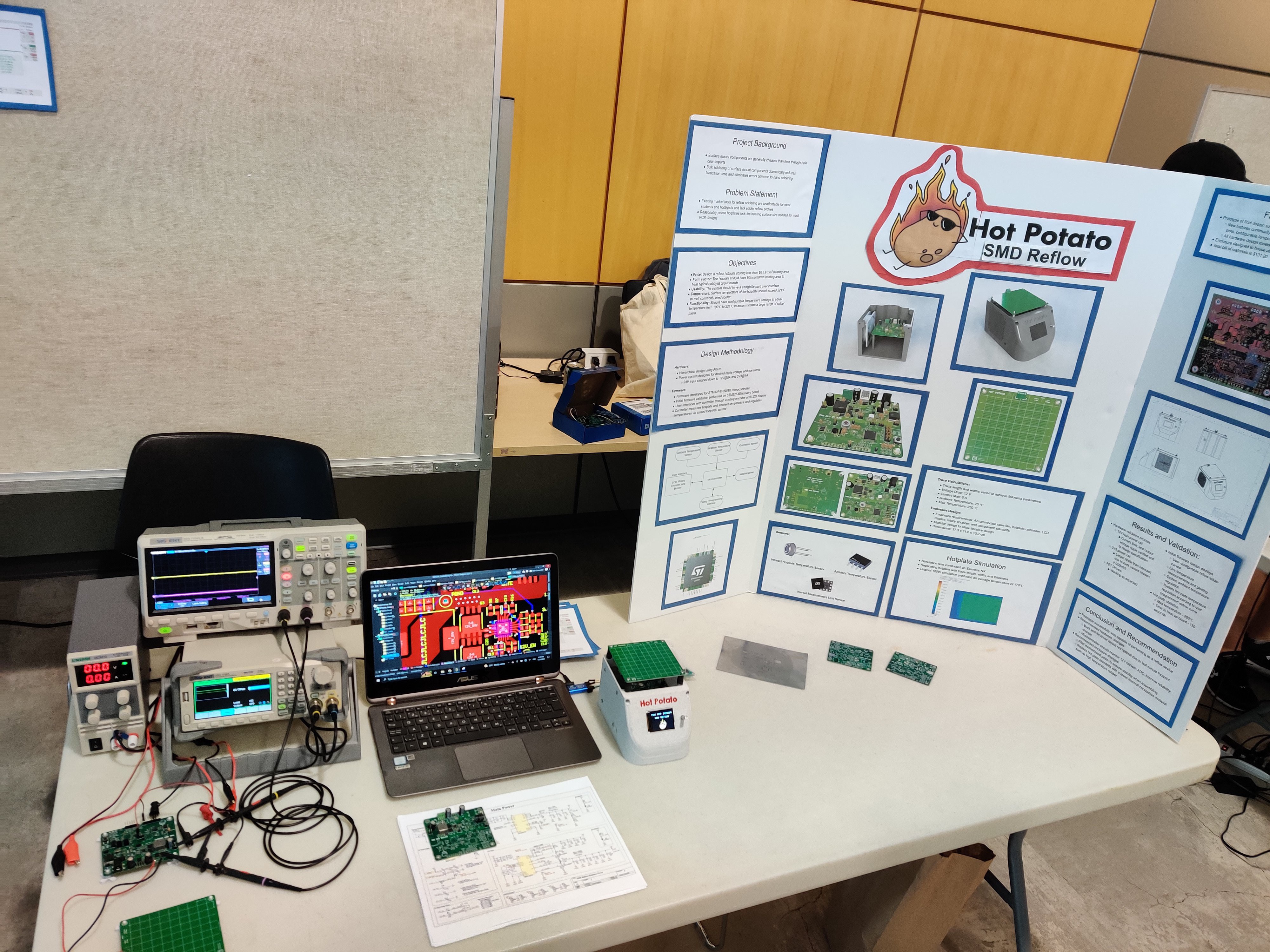
The initial draft for this design has been completed. Apologies for the somewhat sparse documentation; since this project is being completed as part of a course, much of the documentation is being developed by a team of 4 engineering students.
For now, the main hardware and firmware design for this project was completed separately. They were combined for one board, but that resulted in a fried STM32… I now know what the issue was, and I’ll be resolving the issue in a later revision (transients on 3V3 rail). The 100W buck worked perfectly, I originally designed it to be somewhat loosely regulated, since its only used to power the hotplate and case fan. Despite this the 12V rail saw at maximum 200mV peak to peak ripple, and similar transient overshoot/undershoot, even with 9A steps on its output.
In the future I would like to document this validation more rigorously, but for the time being this project will be put onto the back burner until I complete my job search (graduating from university : ) ). Anyhow here is a picture of the project during the demonstration day.

P.S. Big shout out to Joel for troubleshooting the design with me until 2am the night before our demo day
 Jesse Farrell
Discussions
Become a Hackaday.io Member
Create an account to leave a comment. Already have an account? Log In.