 Quinn
QuinnWe can use all of that, distilled down to the basics to do the test without all the switches and sockets.
Test Circuit
The generic test circuit is:
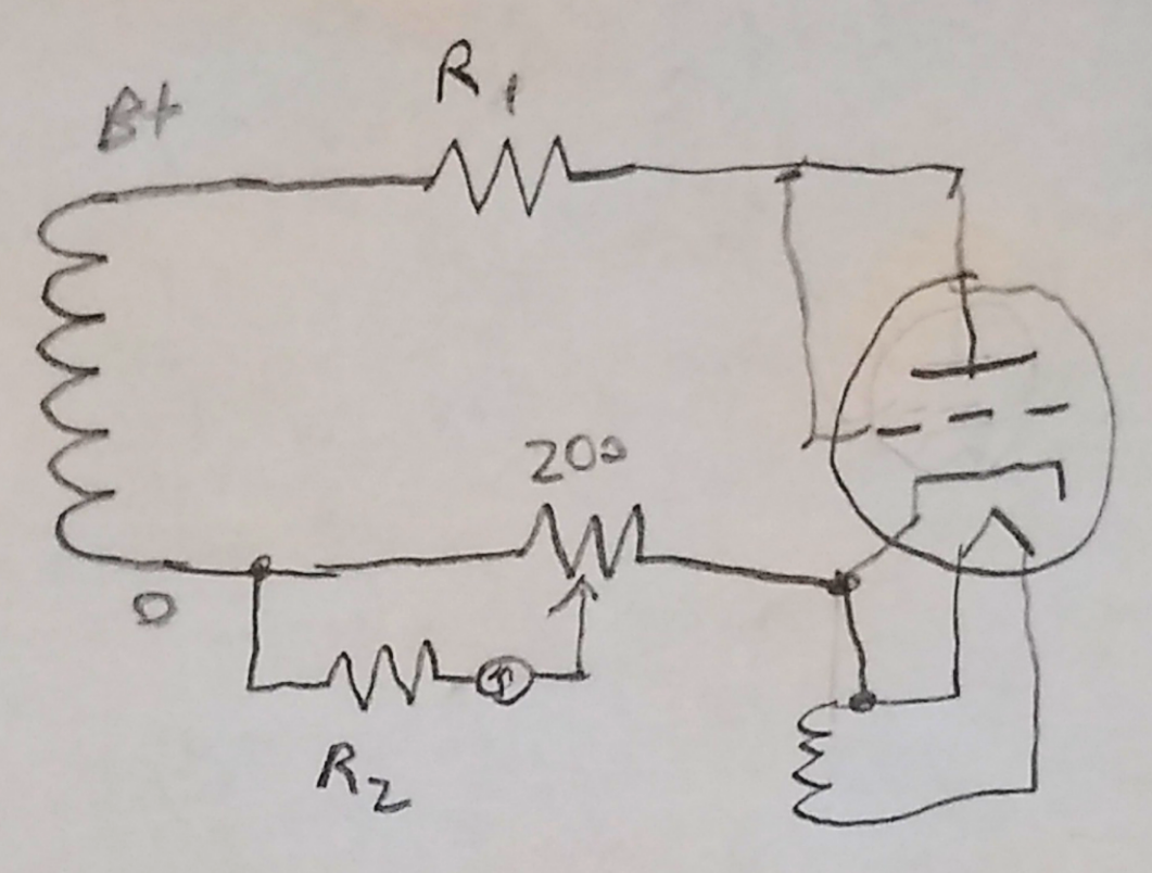
Note that if the device is a pentode or pentagrid converter, all the grids are weird together with the plate.
| Type | B+ | R1 | R2 |
| 1 | 30 | 3600 | 0 |
| 2 | 30 | 820 | 360 |
| 3 | 30 | 0 | 1500 |
| 4 | 250 | 2500 | 1500 |
Looks like R1 could burn some power, so probably best to keep the test short if you can't find 10w ones.
I'll also need a 200 ohm wire wound resistor which I found. If you don't have one, you could use a decade resistor box, or substitute in fixed values. Looks like whatever you pick should be able to tolerate 25mA, or 1.25W (modes 1,2,3 only), which should only happen if the tube has a short.
The original tester uses AC for the supply, relying on the tube as a diode, and the averaging nature of an analog meter to smooth out the pulses. I'll just use DC, which also makes for easy current limiting. I think you can use AC with a digital ammeter, as long as you set it to ac RMS.
We still need to figure out the meter resistance, which we'll get to soon.
Discussions
Become a Hackaday.io Member
Create an account to leave a comment. Already have an account? Log In.